目次
概要
FVRFを利用したVRF-awareなDMVPNにおいて、新しく拠点を追加します。新拠点のルータの設定例です。VRF-awareなDMVPNに関する一連の設定をまとめて行います。
関連記事
ネットワーク構成
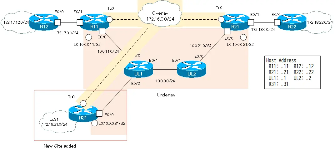
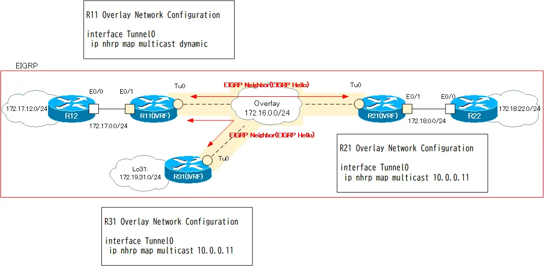
次のネットワーク構成を考えます。このネットワーク構成のアンダーレイネットワークはインターネットではありませんが、インターネットだと想定します。R31が新しく追加された拠点のルータです。
設定条件
R11/R21/R31間でDMVPNのオーバーレイネットワークを構築します。R11はNHSです。R21/R31はNHCです。そして、オーバーレイネットワークとアンダーレイネットワークをVRFで分離します。VRFとして、以下のような設定を行います。
| ルータ | VRF名 | RD | インタフェース |
|---|---|---|---|
| R11 | FVRF | 65001:100 | Lo0 Eth0/0 |
| IVRF | 65001:200 | Tunnel0 Eth0/1 | |
| R21 | FVRF | 65001:100 | Lo0 Eth0/0 |
| IVRF | 65001:200 | Tunnel0 Eth0/1 | |
| R31 | FVRF | 65001:100 | Lo0 Eth0/0 |
| IVRF | 65001:200 | Tunnel0 Lo31 |
また、オーバーレイネットワークのIVRFとアンダーレイネットワークのFVRFのアドレス範囲は、重複しないようにしています。IVRFは、172.16.x.xおよび172.17.x.x、172.18.x.xといったクラスBのプライベートアドレスでアドレッシングしています。そして、FVRFは、10.x.x.xのクラスAのプライベートアドレスでアドレッシングしています。
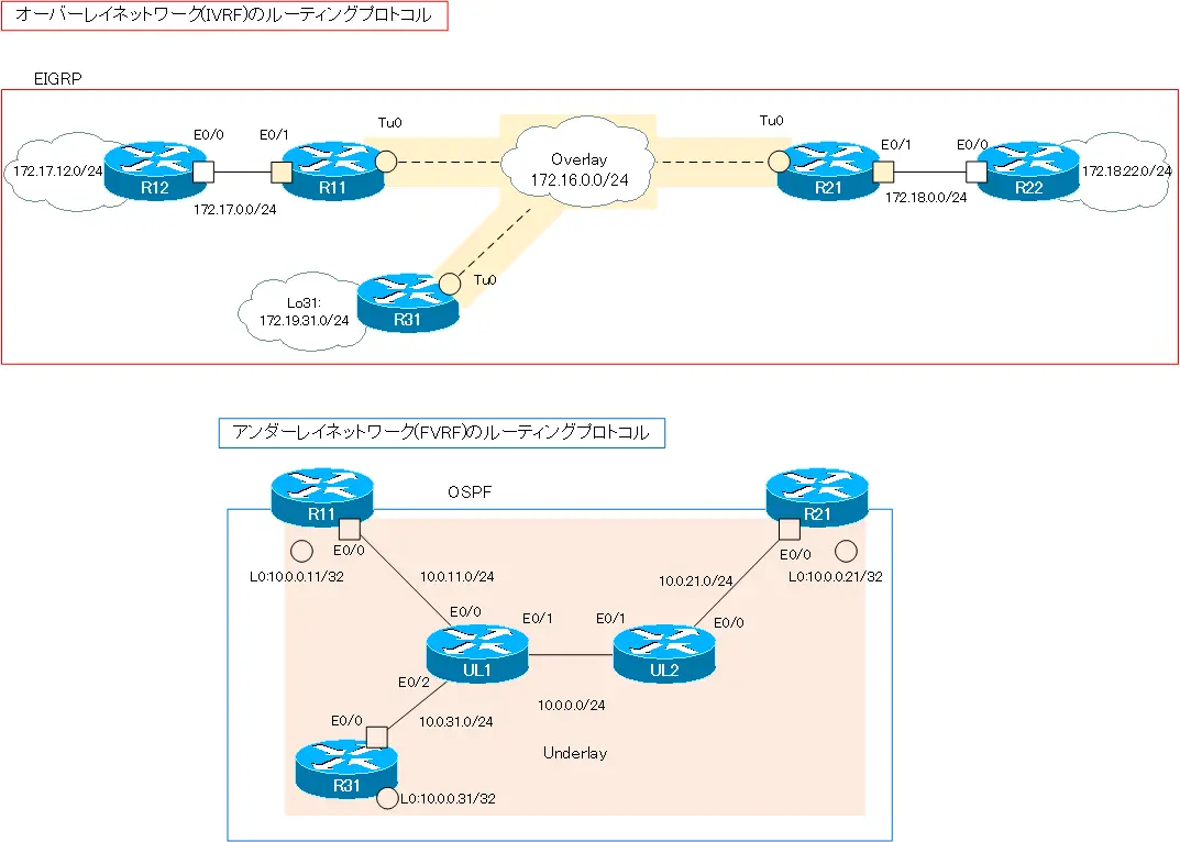
ルーティングプロトコルとして、IVRFはEIGRPを利用し、FVRFではOSPFを利用します。
| アドレス範囲 | ルーティングプロトコル | |
|---|---|---|
| オーバーレイネットワーク(IVRF) | 172.16.0.0/16 172.17.0.0/16 172.18.0.0/16 172.19.0.0/16 | EIGRP |
| アンダーレイネットワーク(FVRF) | 10.0.0.0/8 | OSPF |
オーバーレイネットワークのデータをIPSecで暗号化して、アンダーレイネットワーク上を転送します。IPSecの各種パラメータは、以下の通りとします。
| 暗号化アルゴリズム | 3DES |
| ハッシュアルゴリズム | MD5 |
| ピア認証 | PSK |
| DHグループ | 2 |
| セキュリティプロトコル | ESP |
| 暗号化アルゴリズム | 3DES |
| ハッシュアルゴリズム | MD5 |
初期設定
新しく追加したR31以外の設定はすべて完了している状態から進めます。R31はホスト名だけ設定しています。各ルータのDMVPNに関連する設定は以下の通りです。
R11 設定抜粋(Click)
hostname R11
!
ip vrf FVRF
 rd 65001:100
!
ip vrf IVRF
 rd 65001:200
!
crypto keyring KEY vrf FVRF
  pre-shared-key address 0.0.0.0 0.0.0.0 key cisco
!
crypto isakmp policy 10
 encr 3des
 hash md5
 authentication pre-share
 group 2
!
crypto ipsec transform-set TS esp-3des esp-md5-hmac
 mode transport
!
crypto ipsec profile IPSEC
 set transform-set TS
!
interface Loopback0
 ip vrf forwarding FVRF
 ip address 10.0.0.11 255.255.255.255
!
interface Tunnel0
 ip vrf forwarding IVRF
 ip address 172.16.0.11 255.255.255.0
 no ip redirects
 ip nhrp map multicast dynamic
 ip nhrp network-id 1000
 tunnel source Loopback0
 tunnel mode gre multipoint
 tunnel vrf FVRF
!
interface Ethernet0/0
 ip vrf forwarding FVRF
 ip address 10.0.11.11 255.255.255.0
!
interface Ethernet0/1
 ip vrf forwarding IVRF
 ip address 172.17.0.11 255.255.255.0
!
router eigrp 1
 !
 address-family ipv4 vrf IVRF autonomous-system 1
  network 172.16.0.0
  network 172.17.0.0
 exit-address-family
 eigrp router-id 11.11.11.11
!
router ospf 1 vrf FVRF
 router-id 11.11.11.11
 network 10.0.0.11 0.0.0.0 area 0
 network 10.0.11.11 0.0.0.0 area 0
R21 設定抜粋(Click)
hostname R21
!
ip vrf FVRF
 rd 65100:100
!
ip vrf IVRF
 rd 65100:200
!
crypto keyring KEY vrf FVRF
  pre-shared-key address 0.0.0.0 0.0.0.0 key cisco
!
crypto isakmp policy 10
 encr 3des
 hash md5
 authentication pre-share
 group 2
!
crypto ipsec transform-set TS esp-3des esp-md5-hmac
 mode transport
!
crypto ipsec profile IPSEC
 set transform-set TS
!
interface Loopback0
 ip vrf forwarding FVRF
 ip address 10.0.0.21 255.255.255.255
!
interface Tunnel0
 ip vrf forwarding IVRF
 ip address 172.16.0.21 255.255.255.0
 no ip redirects
 ip nhrp map 172.16.0.11 10.0.0.11
 ip nhrp map multicast 10.0.0.11
 ip nhrp network-id 1000
 ip nhrp nhs 172.16.0.11
 tunnel source Loopback0
 tunnel mode gre multipoint
 tunnel vrf FVRF
!
interface Ethernet0/0
 ip vrf forwarding FVRF
 ip address 10.0.21.21 255.255.255.0
!
interface Ethernet0/1
 ip vrf forwarding IVRF
 ip address 172.18.0.21 255.255.255.0
!
router eigrp 1
 !
 address-family ipv4 vrf IVRF autonomous-system 1
  network 172.16.0.0
  network 172.18.0.0
 exit-address-family
 eigrp router-id 21.21.21.21
!
router ospf 1 vrf FVRF
 router-id 21.21.21.21
 network 10.0.0.21 0.0.0.0 area 0
 network 10.0.21.21 0.0.0.0 area 0
R12 設定抜粋(Click)
hostname R12
!
interface Loopback0
 ip address 172.17.12.12 255.255.255.0
 ip ospf network point-to-point
!
interface Ethernet0/0
 ip address 172.17.0.12 255.255.255.0
!
router eigrp 1
 network 172.17.0.0
 eigrp router-id 12.12.12.12
R22 設定抜粋(Click)
hostname R22
!
interface Loopback0
 ip address 172.18.22.22 255.255.255.0
 ip ospf network point-to-point
!
interface Ethernet0/0
 ip address 172.18.0.22 255.255.255.0
!
router eigrp 1
 network 172.18.0.0
 eigrp router-id 22.22.22.22
UL1 設定抜粋(Click)
hostname UL1
!
interface Ethernet0/0
 ip address 10.0.11.1 255.255.255.0
!
interface Ethernet0/1
 ip address 10.0.0.1 255.255.255.0
!
interface Ethernet0/2
 ip address 10.0.31.1 255.255.255.0
!
router ospf 1
 router-id 1.1.1.1
 network 10.0.0.0 0.255.255.255 area 0
UL2 設定抜粋(Click)
hostname UL2
!
interface Ethernet0/0
 ip address 10.0.21.2 255.255.255.0
!
interface Ethernet0/1
 ip address 10.0.0.2 255.255.255.0
!
router ospf 1
 router-id 2.2.2.2
 network 10.0.0.0 0.255.255.255 area 0
設定と確認
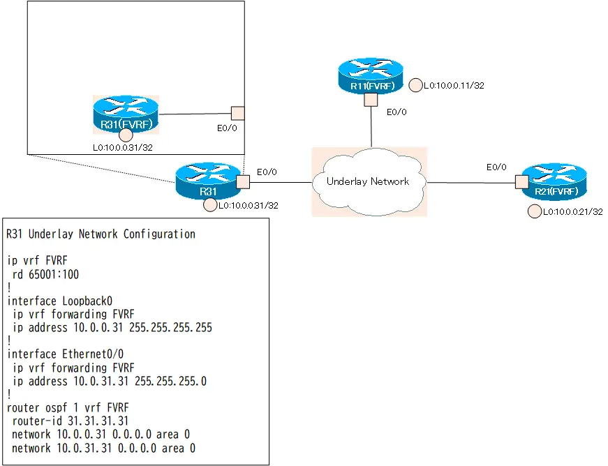
Step1: R31 アンダーレイネットワーク(FVRF)の設定
R31で実際にデータを転送するためのアンダーレイネットワークの設定を行います。アンダーレイネットワーク用のFVRFを作成して、適切なインタフェースをFVRFに割り当てます。そして、OSPFでルーティングを行います。
R31 アンダーレイネットワークの設定
ip vrf FVRF
 rd 65001:100
!
interface Loopback0
 ip vrf forwarding FVRF
 ip address 10.0.0.31 255.255.255.255
!
interface Ethernet0/0
 ip vrf forwarding FVRF
 ip address 10.0.31.31 255.255.255.0
!
router ospf 1 vrf FVRF
 router-id 31.31.31.31
 network 10.0.0.31 0.0.0.0 area 0
 network 10.0.31.31 0.0.0.0 area 0
Step2: R31 アンダーレイネットワーク(FVRF)の確認
R31でのアンダーレイネットワークの設定が正しく動作していることを確認します。次のshowコマンドを利用します。
- show ip vrf detail
- show ip route vrf FVRF
R31 アンダーレイネットワークの確認
R31#show ip vrf detail VRF FVRF (VRF Id = 1); default RD 65001:100; default VPNIDOld CLI format, supports IPv4 only Flags: 0xC Interfaces: Lo0 Et0/0 Address family ipv4 unicast (Table ID = 0x1): Flags: 0x0 No Export VPN route-target communities No Import VPN route-target communities No import route-map No global export route-map No export route-map VRF label distribution protocol: not configured VRF label allocation mode: per-prefix R31#show ip route vrf FVRF Routing Table: FVRF ~省略~ Gateway of last resort is not set 10.0.0.0/8 is variably subnetted, 8 subnets, 2 masks O 10.0.0.0/24 [110/20] via 10.0.31.1, 00:00:50, Ethernet0/0 O 10.0.0.11/32 [110/21] via 10.0.31.1, 00:00:50, Ethernet0/0 O 10.0.0.21/32 [110/31] via 10.0.31.1, 00:00:40, Ethernet0/0 C 10.0.0.31/32 is directly connected, Loopback0 O 10.0.11.0/24 [110/20] via 10.0.31.1, 00:00:50, Ethernet0/0 O 10.0.21.0/24 [110/30] via 10.0.31.1, 00:00:40, Ethernet0/0 C 10.0.31.0/24 is directly connected, Ethernet0/0 L 10.0.31.31/32 is directly connected, Ethernet0/0
これで、R31からアンダーレイネットワークを通じて、R11/R21と通信可能です。
R31 アンダーレイネットワークの通信
R31#ping vrf FVRF 10.0.0.11 source 10.0.0.31
Type escape sequence to abort.
Sending 5, 100-byte ICMP Echos to 10.0.0.11, timeout is 2 seconds:
Packet sent with a source address of 10.0.0.31
!!!!!
Success rate is 100 percent (5/5), round-trip min/avg/max = 1/1/1 ms
R31#ping vrf FVRF 10.0.0.21 source 10.0.0.31
Type escape sequence to abort.
Sending 5, 100-byte ICMP Echos to 10.0.0.21, timeout is 2 seconds:
Packet sent with a source address of 10.0.0.31
!!!!!
Success rate is 100 percent (5/5), round-trip min/avg/max = 1/1/1 ms
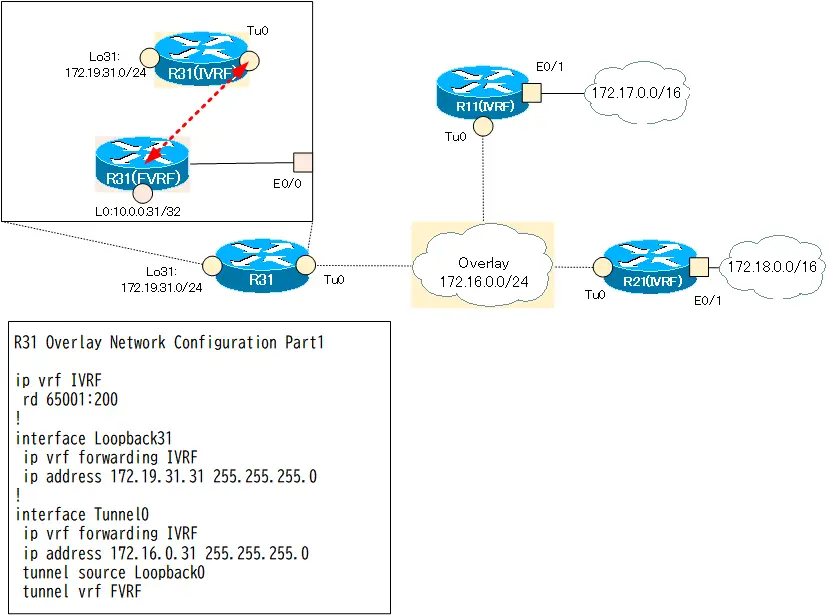
Step3: R31 オーバーレイネットワーク(IVRF)の設定 Part1
R31でオーバーレイネットワーク用のIVRFを作成します。また、Tunnel0を作成します。ひとまず、Tunnel0にはオーバーレイネットワーク用のIPアドレス172.16.0.31/24だけ設定して、NHRPについては後回しにします。
そして、IVRF用のインタフェースとして、Tunnel0とLo31を割り当てます。Tunnel0のデータは、実際にはFVRFを通じて転送します。tunnel vrfコマンドで、Tunnel0とFVRFを関連付けます。
R31 オーバーレイネットワーク(IVRF)の設定 Part1
ip vrf IVRF
 rd 65001:200
!
interface Loopback31
 ip vrf forwarding IVRF
 ip address 172.19.31.31 255.255.255.0
!
interface Tunnel0
 ip vrf forwarding IVRF
 ip address 172.16.0.31 255.255.255.0
 tunnel source Loopback0
 tunnel vrf FVRF
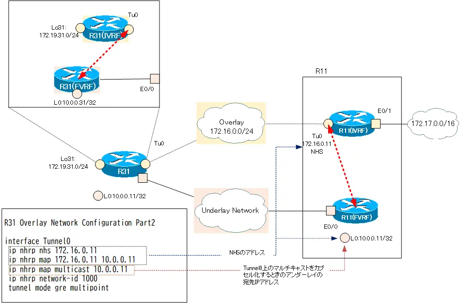
Step4: R31 オーバーレイネットワーク(IVRF)の設定 Part2
R31のTunnel0をmGREにします。R31はNHC(Next Hop Client)です。R11(IVRF)をNHSとして設定します。また、マルチキャストパケットをR11(IVRF)に転送できるように、R11のアンダーレイアドレス(FVRF)でカプセル化します。
R31 オーバーレイネットワーク(IVRF)の設定 Part2
interface Tunnel0
 ip nhrp map multicast 10.0.0.11
 ip nhrp map 172.16.0.11 10.0.0.11
 ip nhrp network-id 1000
 ip nhrp nhs 172.16.0.11
 tunnel mode gre multipoint
これでmGREのNHRPの設定は完了です。
Step5: R31 オーバーレイネットワーク(IVRF)の設定 Part3
あとは、R31のTunnel0のデータをすべてIPSecで暗号化します。IKE Phase1の通信を行うときには、FVRFに基づきます。crypto keyringで事前共有鍵を設定するときにFVRFを指定してください。
R31 オーバーレイネットワーク(IVRF)の設定 Part3
crypto keyring KEY vrf FVRF
  pre-shared-key address 0.0.0.0 0.0.0.0 key cisco
!
crypto isakmp policy 10
 encr 3des
 hash md5
 authentication pre-share
 group 2
!
crypto ipsec transform-set TS esp-3des esp-md5-hmac
 mode transport
!
crypto ipsec profile IPSEC
 set transform-set TS
!
interface Tunnel0
 tunnel protection ipsec profile IPSEC
ここまでの設定で、R31のオーバーレイネットワーク(IVRF)の設定は完了です。
Step6: R31 オーバーレイネットワーク(IVRF)の確認
R31でTunnel0のmGREの設定が正しく動作していることを確認します。以下のshowコマンドを利用します。
- show ip vrf detail IVRF
- show interface tunnel0
- show ip nhrp
- show dmvpn
R31 オーバーレイネットワーク(IVRF)の確認
R31#show ip vrf detail IVRF VRF IVRF (VRF Id = 2); default RD 65001:200; default VPNIDOld CLI format, supports IPv4 only Flags: 0xC Interfaces: Lo31 Tu0 Address family ipv4 unicast (Table ID = 0x2): Flags: 0x0 No Export VPN route-target communities No Import VPN route-target communities No import route-map No global export route-map No export route-map VRF label distribution protocol: not configured VRF label allocation mode: per-prefix R31#show interfaces tunnel 0 Tunnel0 is up, line protocol is up Hardware is Tunnel Internet address is 172.16.0.31/24 MTU 17916 bytes, BW 100 Kbit/sec, DLY 50000 usec, reliability 255/255, txload 1/255, rxload 1/255 Encapsulation TUNNEL, loopback not set Keepalive not set Tunnel linestate evaluation up Tunnel source 10.0.0.31 (Loopback0) Tunnel Subblocks: src-track: Tunnel0 source tracking subblock associated with Loopback0 Set of tunnels with source Loopback0, 1 member (includes iterators), on interface Tunnel protocol/transport multi-GRE/IP Key disabled, sequencing disabled Checksumming of packets disabled Tunnel TTL 255, Fast tunneling enabled Tunnel transport MTU 1476 bytes Tunnel transmit bandwidth 8000 (kbps) Tunnel receive bandwidth 8000 (kbps) Tunnel protection via IPSec (profile "IPSEC") ~省略~ R31#show ip nhrp 172.16.0.11/32 (IVRF) via 172.16.0.11 Tunnel0 created 00:50:23, never expire Type: static, Flags: used NBMA address: 10.0.0.11 R31#show dmvpn Legend: Attrb --> S - Static, D - Dynamic, I - Incomplete N - NATed, L - Local, X - No Socket T1 - Route Installed, T2 - Nexthop-override C - CTS Capable # Ent --> Number of NHRP entries with same NBMA peer NHS Status: E --> Expecting Replies, R --> Responding, W --> Waiting UpDn Time --> Up or Down Time for a Tunnel ========================================================================== Interface: Tunnel0, IPv4 NHRP Details Type:Spoke, NHRP Peers:1, # Ent Peer NBMA Addr Peer Tunnel Add State UpDn Tm Attrb ----- --------------- --------------- ----- -------- ----- 1 10.0.0.11 172.16.0.11 UP 00:49:21 S
オーバーレイネットワークのR11/R21と通信できることも確認します。
R31 オーバーレイネットワーク(IVRF)の通信確認
R31#ping vrf IVRF 172.16.0.11
Type escape sequence to abort.
Sending 5, 100-byte ICMP Echos to 172.16.0.11, timeout is 2 seconds:
!!!!!
Success rate is 100 percent (5/5), round-trip min/avg/max = 5/5/5 ms
R31#ping vrf IVRF 172.16.0.21
Type escape sequence to abort.
Sending 5, 100-byte ICMP Echos to 172.16.0.21, timeout is 2 seconds:
!!!!!
Success rate is 100 percent (5/5), round-trip min/avg/max = 6/9/18 ms
R31#show ip nhrp
172.16.0.11/32 (IVRF) via 172.16.0.11
   Tunnel0 created 00:52:17, never expire
   Type: static, Flags: used
   NBMA address: 10.0.0.11
172.16.0.21/32 (IVRF) via 172.16.0.21
   Tunnel0 created 00:00:04, expire 01:59:55
   Type: dynamic, Flags: router used nhop
   NBMA address: 10.0.0.21
172.16.0.31/32 (IVRF) via 172.16.0.31
   Tunnel0 created 00:00:04, expire 01:59:55
   Type: dynamic, Flags: router unique local
   NBMA address: 10.0.0.31
    (no-socket)
R31#show dmvpn
Legend: Attrb --> S - Static, D - Dynamic, I - Incomplete
        N - NATed, L - Local, X - No Socket
        T1 - Route Installed, T2 - Nexthop-override
        C - CTS Capable
        # Ent --> Number of NHRP entries with same NBMA peer
        NHS Status: E --> Expecting Replies, R --> Responding, W --> Waiting
        UpDn Time --> Up or Down Time for a Tunnel
==========================================================================

Interface: Tunnel0, IPv4 NHRP Details
Type:Spoke, NHRP Peers:2,

 # Ent  Peer NBMA Addr Peer Tunnel Add State  UpDn Tm Attrb
 ----- --------------- --------------- ----- -------- -----
     1 10.0.0.11           172.16.0.11    UP 00:51:16     S
     1 10.0.0.21           172.16.0.21    UP 00:00:07     D
R31からR21宛てにデータを送信するときに、NHRPでR21のアンダーレイアドレスを解決しています。そして、ダイナミックにDMVPNのピアを確立しています。
ただ、この段階では、オーバーレイネットワークを経由したR11/R21の配下の172.17.0.0/16、172.18.0.0/16宛ての通信はできません。オーバーレイネットワークでEIGRPを設定しなければいけません。
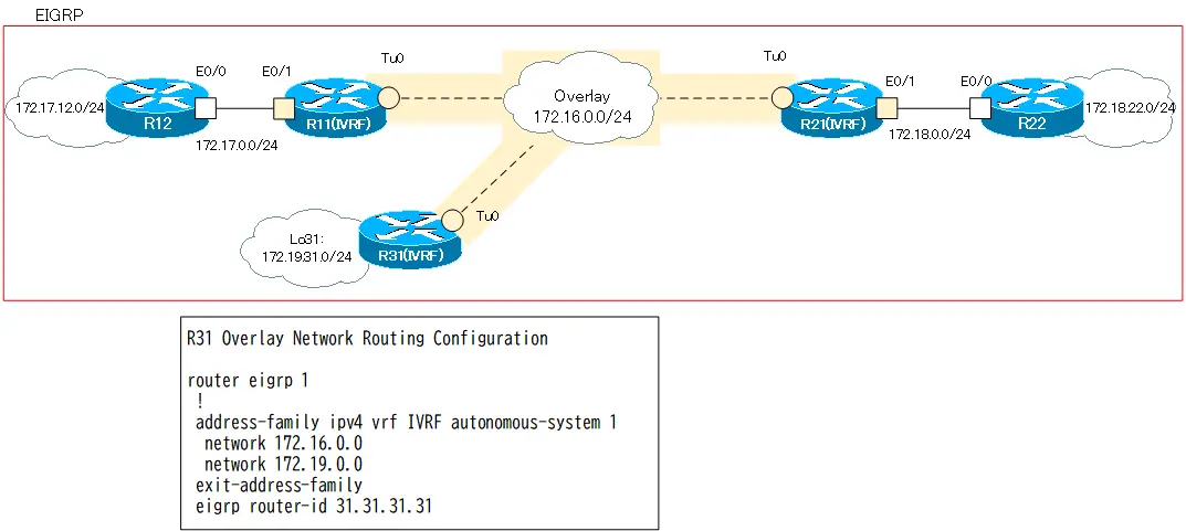
Step7: R31 オーバーレイネットワーク(IVRF)のEIGRPの設定
R31のオーバーレイネットワーク(IVRF)でEIGRPによるルーティングを行います。
R31 オーバーレイネットワーク(IVRF)のEIGRPの設定
router eigrp 1
 !
 address-family ipv4 vrf IVRF autonomous-system 1
  network 172.16.0.0
  network 172.19.0.0
 exit-address-family
 eigrp router-id 31.31.31.31
Step8: R31 オーバーレイネットワーク(IVRF)のEIGRPの確認
R31のオーバーレイネットワークのEIGRPの設定を確認します。以下のshowコマンドを利用します。
- show ip eigrp vrf IVRF neighbor
- show ip route vrf IVRF
R31 オーバーレイネットワーク(IVRF)のEIGRPの確認
R31#show ip eigrp vrf IVRF neighbors
EIGRP-IPv4 Neighbors for AS(1) VRF(IVRF)
H   Address                 Interface              Hold Uptime   SRTT   RTO  Q  Seq
                                                   (sec)         (ms)       Cnt Num
0   172.16.0.11             Tu0                      13 00:02:06   58  1470  0  25
R31#show ip route vrf IVRF

Routing Table: IVRF
~省略~

Gateway of last resort is not set

      172.16.0.0/16 is variably subnetted, 2 subnets, 2 masks
C        172.16.0.0/24 is directly connected, Tunnel0
L        172.16.0.31/32 is directly connected, Tunnel0
      172.17.0.0/24 is subnetted, 2 subnets
D        172.17.0.0 [90/26905600] via 172.16.0.11, 00:02:10, Tunnel0
D        172.17.12.0 [90/27033600] via 172.16.0.11, 00:02:10, Tunnel0
      172.19.0.0/16 is variably subnetted, 2 subnets, 2 masks
C        172.19.31.0/24 is directly connected, Loopback31
L        172.19.31.31/32 is directly connected, Loopback31
R31はR11とのみEIGRPネイバーになっています。R21とはEIGRPネイバーになっていません。
mGREトンネルはノンブロードキャストマルチアクセスネットワークです。マルチキャストパケットの転送先を明示的に決めなければいけません。そのために、ip nhrp map multicastコマンドでカプセル化するアンダーレイアドレスを設定しています。R31では、マルチキャストパケットをR11に転送する設定のみです。EIGRP HelloパケットはR11だけに届きます。そのため、R31はR11とのみEIGRPネイバーになっています。R21も同様です。つまり、EIGRPの観点からmGREトンネルのオーバーレイネットワークはR11を中心とするハブ&スポークトポロジです。
ハブ&スポークとなっているのは、あくまでもEIGRPの観点(マルチキャスト)からです。ユニキャストの通信はNHRPによってフルメッシュです。
R11は、スプリットホライズンによってR21から受信したEIGRPルートをR31にはアドバタイズしません。同様にR31から受信したEIGRPルートをR21にはアドバタイズしません。R11配下の172.17.0.0/16との通信は可能です。しかし、R21配下の172.18.0.0/16とR31配下の172.19.0.0/16の通信はできない状態です。
R31 通信確認
R31#ping vrf IVRF 172.17.12.12 source 172.19.31.31
Type escape sequence to abort.
Sending 5, 100-byte ICMP Echos to 172.17.12.12, timeout is 2 seconds:
Packet sent with a source address of 172.19.31.31
!!!!!
Success rate is 100 percent (5/5), round-trip min/avg/max = 2/5/7 ms
R31#ping vrf IVRF 172.18.22.22 source 172.19.31.31
Type escape sequence to abort.
Sending 5, 100-byte ICMP Echos to 172.18.22.22, timeout is 2 seconds:
Packet sent with a source address of 172.19.31.31
.....
Success rate is 0 percent (0/5)
NHCのR21/R31間でマルチキャストパケットを転送できるように、ip nhrp map multicastコマンドを追加すれば、R21-R31間もEIGRPネイバーになりフルメッシュにできます。ですが、NHCがたくさんあるとすべてのNHC間でip nhrp map multicastでマルチキャストパケットを転送する設定を行うのは煩雑になってしまいます。
Step9: ハブ&スポーク EIGRPの設定
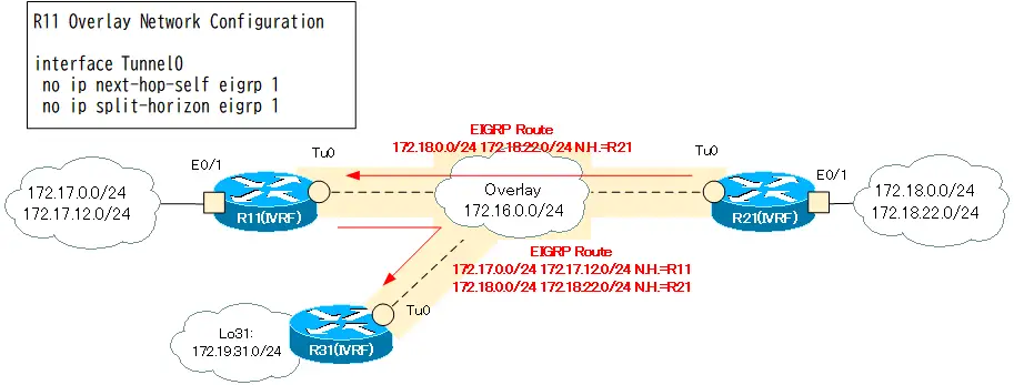
R11をハブとするハブ&スポークトポロジでEIGRPを利用してルート情報をアドバタイズできるようにします。R11 Tunnel0でスプリットホライズンを無効にし、ネクストホップを変更しないようにします。
R11 ハブ&スポーク EIGRP
interface Tunnel0
 no ip next-hop-self eigrp 1
 no ip split-horizon eigrp 1
この設定によって、R21(IVRF)からアドバタイズされたEIGRPルートは、R31(IVRF)まで届くようになります。R31(IVRF)からアドバタイズされたEIGRPルートも同様にR21(IVRF)まで届くようになります。
Step10: ハブ&スポーク EIGRPの確認
R11でハブ&スポークとしてEIGRPの設定を行っているので、R31のルーティングテーブルは以下のようになります。
R31 ルーティングテーブル
R31#show ip route vrf IVRF

Routing Table: IVRF
~省略~

Gateway of last resort is not set

      172.16.0.0/16 is variably subnetted, 2 subnets, 2 masks
C        172.16.0.0/24 is directly connected, Tunnel0
L        172.16.0.31/32 is directly connected, Tunnel0
      172.17.0.0/24 is subnetted, 2 subnets
D        172.17.0.0 [90/26905600] via 172.16.0.11, 00:07:45, Tunnel0
D        172.17.12.0 [90/27033600] via 172.16.0.11, 00:07:45, Tunnel0
      172.18.0.0/24 is subnetted, 2 subnets
D        172.18.0.0 [90/28185600] via 172.16.0.21, 00:07:45, Tunnel0
D        172.18.22.0 [90/28313600] via 172.16.0.21, 00:07:45, Tunnel0
      172.19.0.0/16 is variably subnetted, 2 subnets, 2 masks
C        172.19.31.0/24 is directly connected, Loopback31
L        172.19.31.31/32 is directly connected, Loopback31
これでDMVPNへの新サイト(R31)の追加の設定はすべて正しく完了です。
R31-R21間の通信もできるようになっています。
R31 通信確認
R31#ping vrf IVRF 172.17.12.12 source 172.19.31.31
Type escape sequence to abort.
Sending 5, 100-byte ICMP Echos to 172.17.12.12, timeout is 2 seconds:
Packet sent with a source address of 172.19.31.31
!!!!!
Success rate is 100 percent (5/5), round-trip min/avg/max = 2/5/6 ms
R31#ping vrf IVRF 172.18.22.22 source 172.19.31.31
Type escape sequence to abort.
Sending 5, 100-byte ICMP Echos to 172.18.22.22, timeout is 2 seconds:
Packet sent with a source address of 172.19.31.31
!!!!!
Success rate is 100 percent (5/5), round-trip min/avg/max = 5/7/10 ms
設定のまとめ
新しく追加したR31の設定のまとめです。
R31 VRF-aware DMVPN
hostname R31
!
ip vrf FVRF
 rd 65001:100
!
ip vrf IVRF
 rd 65001:200
!
crypto keyring KEY vrf FVRF
  pre-shared-key address 0.0.0.0 0.0.0.0 key cisco
!
crypto isakmp policy 10
 encr 3des
 hash md5
 authentication pre-share
 group 2
!
crypto ipsec transform-set TS esp-3des esp-md5-hmac
 mode transport
!
crypto ipsec profile IPSEC
 set transform-set TS
!
interface Loopback0
 ip vrf forwarding FVRF
 ip address 10.0.0.31 255.255.255.255
!
interface Loopback31
 ip vrf forwarding IVRF
 ip address 172.19.31.31 255.255.255.0
!
interface Tunnel0
 ip vrf forwarding IVRF
 ip address 172.16.0.31 255.255.255.0
 no ip redirects
 ip nhrp map multicast 10.0.0.11
 ip nhrp map 172.16.0.11 10.0.0.11
 ip nhrp network-id 1000
 ip nhrp nhs 172.16.0.11
 tunnel source Loopback0
 tunnel mode gre multipoint
 tunnel vrf FVRF
 tunnel protection ipsec profile IPSEC
!
interface Ethernet0/0
 ip vrf forwarding FVRF
 ip address 10.0.31.31 255.255.255.0
!
router eigrp 1
 !
 address-family ipv4 vrf IVRF autonomous-system 1
  network 172.16.0.0
  network 172.19.0.0
 exit-address-family
 eigrp router-id 31.31.31.31
!
router ospf 1 vrf FVRF
 router-id 31.31.31.31
 network 10.0.0.31 0.0.0.0 area 0
 network 10.0.31.31 0.0.0.0 area 0
そして、R11のEIGRPの設定の変更です。
R11 ハブ&スポーク EIGRP
interface Tunnel0
 no ip next-hop-self eigrp 1
 no ip split-horizon eigrp 1
IPルーティング応用
- DNSラウンドロビン方式の負荷分散
- 負荷分散装置(ロードバランサ)の仕組み
- ルーティングプロセス ~実行中のルーティングプロトコル用のプログラム~
- 複数のルーティングプロトコルの利用
- 再配送(再配布) ~ルーティングドメイン境界で必須の設定~
- Cisco再配送(再配布)の設定 ~redistributeコマンド~
- Cisco 再配送の設定例 ~OSPFとRIPの双方向再配送~
- 再配送 設定ミスの切り分けと修正 Part1
- 再配送 設定ミスの切り分けと修正 Part2
- 再配送 設定ミスの切り分けと修正 Part3
- 再配送 設定ミスの切り分けと修正 Part4
- 再配送 設定ミスの切り分けと修正 Part5
- 再配送 設定ミスの切り分けと修正 Part6
- オフセットリスト(offset-list) ~ルート情報のメトリックを加算~
- オフセットリストの設定例 RIP
- オフセットリストの設定例 EIGRP
- ルートフィルタの概要
- ルートフィルタのポイント
- ディストリビュートリストによるルートフィルタの設定
- Ciscoディストリビュートリストによるルートフィルタの設定例
- プレフィクスリスト(prefix-list)によるルートフィルタの設定
- Ciscoプレフィクスリストによるルートフィルタの設定例
- Ciscoルートマップ(route-map)の概要 ~何をどう処理するか~
- Ciscoルートマップの設定
- Ciscoルートマップ(route-map)設定のポイント
- Ciscoルートマップによる再配送時のルート制御の設定例
- ポリシーベースルーティングの設定例
- GREトンネルインタフェース ~仮想的なポイントツーポイント接続~
- GREトンネルインタフェースの設定例
- GREトンネルの注意点 ~フラッピングしないように~
- オーバーレイネットワークとアンダーレイネットワーク
- ルート制御 ケーススタディ Part1
- ルート制御 ケーススタディ Part2
- ルート制御 ケーススタディ Part3
- VRF/VRF-Liteの概要 ~仮想的にルータを分割する~
- VRFの設定と確認コマンド [Cisco]
- VRF-Liteによるレイヤ3VPNの設定例 [Cisco]
- VRFルートリーク(スタティックルート)
- VRFルートリーク(スタティックルート)の設定例
- VRFルートリーク(MP-BGP)
- VRFルートリーク(MP-BGP)の設定例
- [FVRFの仕組み] FVRF(Front door VRF)とは
- [FVRFの仕組み] ポイントツーポイントGREトンネル:FVRFなし
- [FVRFの仕組み] ポイントツーポイントGREトンネル : FVRFあり(tunnel vrfコマンド)
- [FVRFの仕組み] IPSec VTI : FRVRFあり
- [FVRFの仕組み] IPSec VTI : FVRFあり 設定例
- [FVRFの仕組み] DMVPN : FVRFあり
- [FVRFの仕組み] DMVPN : FVRFあり 設定例 Part1
- [FVRFの仕組み] DMVPN : FVRFあり 設定例 Part2
- tunnel vrfコマンド
- tunnel vrfコマンドの設定例
- [演習] ルーティングループの防止
- [演習] 企業ネットワーク構築演習 Part1:拠点1の構築
- [演習] 企業ネットワーク構築演習 Part2:拠点2/拠点3の構築
- [演習] 企業ネットワーク構築演習 Part3:広域イーサネットの接続
- [演習] 企業ネットワーク構築演習 Part4:インターネット(AS1/AS2)の構築
- [演習] 企業ネットワーク構築演習 Part5:インターネットへの接続
- [演習] 企業ネットワーク構築演習 Part6:インターネットVPNの構築