目次
概要
tunnel destinationを解決するためにVRFのルーティングテーブルを参照するtunnel vrfコマンドの設定を行います。
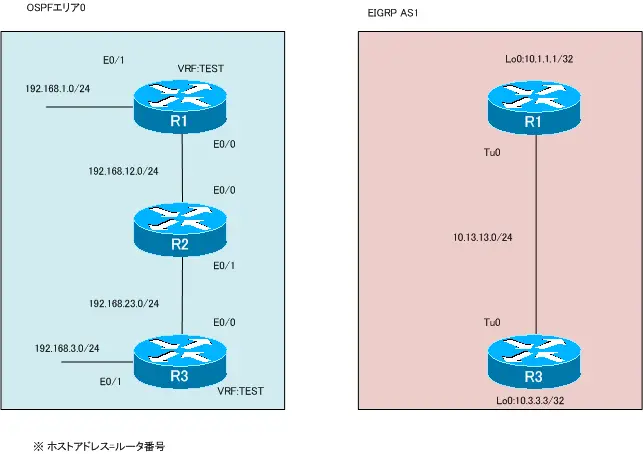
ネットワーク構成
設定条件
- R1とR3でVRF「TEST」を作成してください。RDは100:100とします。
- ネットワーク構成にしたがって、R1とR3でVRFをインタフェースに割り当ててIPアドレスを設定してください。
- R1とR3でスタティックトンネルTunnel0を作成してください。カプセル化するIPアドレスはVRF「TEST」に含まれるE0/1を利用します。
- R1(VRF TEST)、R2、R3(VRF TEST)でOSPFのルーティングを行います。ルータIDは「x.x.x.x」(x=ルータ番号)とします。
- R1、R3でEIGRP AS1のルーティングを行います。
初期設定
以下の設定は設定済みの状態から開始します。
- ホスト名
- IPアドレス
R1 Lo0、R3 Lo0 - R2の設定は完了
設定ファイルダウンロード
- 初期設定の設定ファイル tunnel-vrf-init.zip
- 設定完了時の設定ファイル tunnel-vrf-comp.zip
設定と確認
【Step1:VRFの作成とインタフェースの割り当て】
R1とR3でVRF「TEST」を作成します。そして、E0/0、E0/1をVRF「TEST」に割り当ててIPアドレスを設定します。
R1
ip vrf TEST
 rd 100:100
!
interface Ethernet0/0
 ip vrf forwarding TEST
 ip address 192.168.12.1 255.255.255.0
!
interface Ethernet0/1
 ip vrf forwarding TEST
 ip address 192.168.1.1 255.255.255.0
R3
ip vrf TEST
 rd 100:100
!
interface Ethernet0/0
 ip vrf forwarding TEST
 ip address 192.168.23.3 255.255.255.0
!
interface Ethernet0/1
 ip vrf forwarding TEST
 ip address 192.168. 3.3 255.255.255.0
【Step2:VRFの確認】
R1、R3でVRFと割り当てているインタフェースを確認します。
R1
R1#show ip vrf
  Name                             Default RD          Interfaces
  TEST                             100:100             Et0/0
                                                       Et0/1
R1#show ip interface brief
Interface                  IP-Address      OK? Method Status                Protocol
Ethernet0/0                192.168.12.1    YES manual up                    up
Ethernet0/1                192.168.1.1     YES manual up                    up
Ethernet0/2                unassigned      YES unset  administratively down down
Ethernet0/3                unassigned      YES unset  administratively down down
Loopback0                  10.1.1.1        YES manual up                    up
R1#show ip route vrf TEST

Routing Table: TEST
Codes: C - connected, S - static, R - RIP, M - mobile, B - BGP
       D - EIGRP, EX - EIGRP external, O - OSPF, IA - OSPF inter area
       N1 - OSPF NSSA external type 1, N2 - OSPF NSSA external type 2
       E1 - OSPF external type 1, E2 - OSPF external type 2
       i - IS-IS, su - IS-IS summary, L1 - IS-IS level-1, L2 - IS-IS level-2
       ia - IS-IS inter area, * - candidate default, U - per-user static route
       o - ODR, P - periodic downloaded static route

Gateway of last resort is not set

C    192.168.12.0/24 is directly connected, Ethernet0/0
C    192.168.1.0/24 is directly connected, Ethernet0/1
R3
R3#show ip vrf
  Name                             Default RD          Interfaces
  TEST                             100:100             Et0/0
                                                       Et0/1
R3#show ip interface brief
Interface                  IP-Address      OK? Method Status                Protocol
Ethernet0/0                192.168.23.3    YES manual up                    up
Ethernet0/1                192.168.3.3     YES manual up                    up
Ethernet0/2                unassigned      YES unset  administratively down down
Ethernet0/3                unassigned      YES unset  administratively down down
Loopback0                  10.3.3.3        YES manual up                    up
R3#show ip route vrf TEST

Routing Table: TEST
Codes: C - connected, S - static, R - RIP, M - mobile, B - BGP
       D - EIGRP, EX - EIGRP external, O - OSPF, IA - OSPF inter area
       N1 - OSPF NSSA external type 1, N2 - OSPF NSSA external type 2
       E1 - OSPF external type 1, E2 - OSPF external type 2
       i - IS-IS, su - IS-IS summary, L1 - IS-IS level-1, L2 - IS-IS level-2
       ia - IS-IS inter area, * - candidate default, U - per-user static route
       o - ODR, P - periodic downloaded static route

Gateway of last resort is not set

C    192.168.23.0/24 is directly connected, Ethernet0/0
C    192.168.3.0/24 is directly connected, Ethernet0/1
【Step3:VRF TEST OSPFの設定】
R1、R#のVRF「TEST」でOSPFによるルーティングを行います。ルータIDとして、「x.x.x.x」(x=1 or 3)を設定して、E0/0、E0/1でOSPFを有効化します。
R1
router ospf 1 vrf TEST
 router-id 1.1.1.1
 log-adjacency-changes
 network 192.168.0.0 0.0.255.255 area 0
R3
router ospf 1 vrf TEST
 router-id 3.3.3.3
 log-adjacency-changes
 network 192.168.0.0 0.0.255.255 area 0
【Step4:VRF TEST OSPFの確認】
R1 VRF TEST、R2、R3 VRF TEST間でOSPFによるルーティンができていることを確認します。R2でルーティングテーブルを確認すると、R1とR3からOSPFでルート情報を学習できていることがわかります。
R2
R2#show ip ospf neighbor

Neighbor ID     Pri   State           Dead Time   Address         Interface
3.3.3.3           1   FULL/BDR        00:00:34    192.168.23.3    Ethernet0/1
1.1.1.1           1   FULL/BDR        00:00:34    192.168.12.1    Ethernet0/0
R2#show ip route ospf
O    192.168.1.0/24 [110/20] via 192.168.12.1, 00:01:36, Ethernet0/0
O    192.168.3.0/24 [110/20] via 192.168.23.3, 00:01:36, Ethernet0/1
【Step5:tunnelインタフェースの作成】
R1、R3でTunnel0インタフェースを作成します。Tunnel0はVRF「TEST」ではなく、グローバルルーティングプロセスのインタフェースです。
tunnel destinationとtunnel destinationはE0/0のIPアドレスを利用します。また、Tunnel0インタフェースには、10.13.13.x/24(x=1 or 3)を設定します。
R1
interface Tunnel0
 ip address 10.13.13.1 255.255.255.0
 tunnel source Ethernet0/0
 tunnel destination 192.168.23.3
R3
interface Tunnel0
 ip address 10.13.13.3 255.255.255.0
 tunnel source Ethernet0/0
 tunnel destination 192.168.12.1
【Step6:tunnelインタフェースの確認】
Step5で設定したR1、R3のTunnel0インタフェースの状態を確認します。
R1
R1#show interfaces tunnel 0
Tunnel0 is up, line protocol is down
  Hardware is Tunnel
  Internet address is 10.13.13.1/24
  MTU 1514 bytes, BW 9 Kbit/sec, DLY 500000 usec,
     reliability 255/255, txload 1/255, rxload 1/255
  Encapsulation TUNNEL, loopback not set
  Keepalive not set
  Tunnel source 192.168.12.1 (Ethernet0/0), destination 192.168.23.3
  Tunnel protocol/transport GRE/IP
    Key disabled, sequencing disabled
    Checksumming of packets disabled
  Tunnel TTL 255
~省略~
R3
R3#show interfaces tunnel 0
Tunnel0 is up, line protocol is down
  Hardware is Tunnel
  Internet address is 10.13.13.3/24
  MTU 1514 bytes, BW 9 Kbit/sec, DLY 500000 usec,
     reliability 255/255, txload 1/255, rxload 1/255
  Encapsulation TUNNEL, loopback not set
  Keepalive not set
  Tunnel source 192.168.23.3 (Ethernet0/0), destination 192.168.12.1
  Tunnel protocol/transport GRE/IP
    Key disabled, sequencing disabled
    Checksumming of packets disabled
  Tunnel TTL 255
~省略=
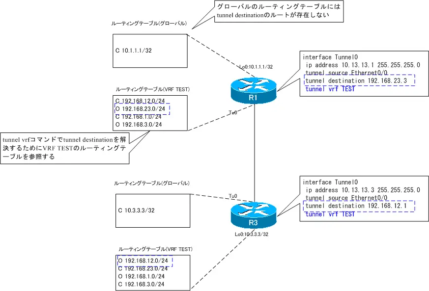
Tunnel0インタフェースはup/downの状態です。これはtunnel destinationのIPアドレスに到達できないためです。tunnel destinationで利用するR1、R3 E0/0はVRF TESTのインタフェースです。Tunnel0インタフェースはグローバルルーティングテーブルに含まれているので、tunnel destinationのIPアドレスを解決できません。そのため、Tunnel0インタフェースはup/downの状態です。
【Step7:tunnel vrfコマンドの設定】
tunnel vrfコマンドによって、VRFのルーティングテーブルからtunnel destinationのIPアドレスを解決できます。R1、R3のTunnel0インタフェースでtunnel vrf TESTコマンドでVRF TESTのルーティングテーブルからtunnel destinationを解決できるようにします。
R1/R3
interface Tunnel0
 tunnel vrf TEST
【Step8:tunnelインタフェースの確認】
再度、R1、R3のtunnelインタフェースの状態を確認します。
R1
R1#show interfaces Tunnel 0
Tunnel0 is up, line protocol is up
  Hardware is Tunnel
  Internet address is 10.13.13.1/24
  MTU 1514 bytes, BW 9 Kbit/sec, DLY 500000 usec,
     reliability 255/255, txload 1/255, rxload 1/255
  Encapsulation TUNNEL, loopback not set
  Keepalive not set
  Tunnel source 192.168.12.1 (Ethernet0/0), destination 192.168.23.3
  Tunnel protocol/transport GRE/IP
    Key disabled, sequencing disabled
    Checksumming of packets disabled
  Tunnel TTL 255
~省略=
R3
R3#show interfaces Tunnel 0
Tunnel0 is up, line protocol is up
  Hardware is Tunnel
  Internet address is 10.13.13.3/24
  MTU 1514 bytes, BW 9 Kbit/sec, DLY 500000 usec,
     reliability 255/255, txload 1/255, rxload 1/255
  Encapsulation TUNNEL, loopback not set
  Keepalive not set
  Tunnel source 192.168.23.3 (Ethernet0/0), destination 192.168.12.1
  Tunnel protocol/transport GRE/IP
    Key disabled, sequencing disabled
    Checksumming of packets disabled
  Tunnel TTL 255
~省略~
tunnel vrfコマンドによってtunnel destinationのIPアドレスを解決できるようになったので、Tunnel0インタフェースがup/upの状態です。
【Step9:EIGRPの設定】
R1、R3ではグローバルのルーティングインスタンス上でTunnel0インタフェースを通じて、EIGRPでルーティングできるようにします。EIGRP AS1を設定します。
R1/R3
router eigrp 1
 network 10.0.0.0
 no auto-summary
【Step10:EIGRPの確認】
R1、R3のグローバルルーティングインスタンスでのEIGRPの設定を確認します。
R1
R1#show ip eigrp neighbors
IP-EIGRP neighbors for process 1
H   Address                 Interface       Hold Uptime   SRTT   RTO  Q  Seq
                                            (sec)         (ms)       Cnt Num
0   10.13.13.3              Tu0               12 00:01:37   79  5000  0  3
R1#show ip route eigrp
     10.0.0.0/8 is variably subnetted, 3 subnets, 2 masks
D       10.3.3.3/32 [90/297372416] via 10.13.13.3, 00:01:39, Tunnel0
【Step11:通信確認】
VRF TESTとグローバルのルーティングインスタンスでの最終的な通信ができることを確認します。
R1
R1#ping 10.3.3.3 source 10.1.1.1

Type escape sequence to abort.
Sending 5, 100-byte ICMP Echos to 10.3.3.3, timeout is 2 seconds:
Packet sent with a source address of 10.1.1.1
!!!!!
Success rate is 100 percent (5/5), round-trip min/avg/max = 20/36/44 ms
R1#ping vrf TEST 192.168.3.3 source 192.168.1.1

Type escape sequence to abort.
Sending 5, 100-byte ICMP Echos to 192.168.3.3, timeout is 2 seconds:
Packet sent with a source address of 192.168.1.1
!!!!!
IPルーティング応用
- DNSラウンドロビン方式の負荷分散
- 負荷分散装置(ロードバランサ)の仕組み
- ルーティングプロセス ~実行中のルーティングプロトコル用のプログラム~
- 複数のルーティングプロトコルの利用
- 再配送(再配布) ~ルーティングドメイン境界で必須の設定~
- Cisco再配送(再配布)の設定 ~redistributeコマンド~
- Cisco 再配送の設定例 ~OSPFとRIPの双方向再配送~
- 再配送 設定ミスの切り分けと修正 Part1
- 再配送 設定ミスの切り分けと修正 Part2
- 再配送 設定ミスの切り分けと修正 Part3
- 再配送 設定ミスの切り分けと修正 Part4
- 再配送 設定ミスの切り分けと修正 Part5
- 再配送 設定ミスの切り分けと修正 Part6
- オフセットリスト(offset-list) ~ルート情報のメトリックを加算~
- オフセットリストの設定例 RIP
- オフセットリストの設定例 EIGRP
- ルートフィルタの概要
- ルートフィルタのポイント
- ディストリビュートリストによるルートフィルタの設定
- Ciscoディストリビュートリストによるルートフィルタの設定例
- プレフィクスリスト(prefix-list)によるルートフィルタの設定
- Ciscoプレフィクスリストによるルートフィルタの設定例
- Ciscoルートマップ(route-map)の概要 ~何をどう処理するか~
- Ciscoルートマップの設定
- Ciscoルートマップ(route-map)設定のポイント
- Ciscoルートマップによる再配送時のルート制御の設定例
- ポリシーベースルーティングの設定例
- GREトンネルインタフェース ~仮想的なポイントツーポイント接続~
- GREトンネルインタフェースの設定例
- GREトンネルの注意点 ~フラッピングしないように~
- オーバーレイネットワークとアンダーレイネットワーク
- ルート制御 ケーススタディ Part1
- ルート制御 ケーススタディ Part2
- ルート制御 ケーススタディ Part3
- VRF/VRF-Liteの概要 ~仮想的にルータを分割する~
- VRFの設定と確認コマンド [Cisco]
- VRF-Liteによるレイヤ3VPNの設定例 [Cisco]
- VRFルートリーク(スタティックルート)
- VRFルートリーク(スタティックルート)の設定例
- VRFルートリーク(MP-BGP)
- VRFルートリーク(MP-BGP)の設定例
- [FVRFの仕組み] FVRF(Front door VRF)とは
- [FVRFの仕組み] ポイントツーポイントGREトンネル:FVRFなし
- [FVRFの仕組み] ポイントツーポイントGREトンネル : FVRFあり(tunnel vrfコマンド)
- [FVRFの仕組み] IPSec VTI : FRVRFあり
- [FVRFの仕組み] IPSec VTI : FVRFあり 設定例
- [FVRFの仕組み] DMVPN : FVRFあり
- [FVRFの仕組み] DMVPN : FVRFあり 設定例 Part1
- [FVRFの仕組み] DMVPN : FVRFあり 設定例 Part2
- tunnel vrfコマンド
- tunnel vrfコマンドの設定例
- [演習] ルーティングループの防止
- [演習] 企業ネットワーク構築演習 Part1:拠点1の構築
- [演習] 企業ネットワーク構築演習 Part2:拠点2/拠点3の構築
- [演習] 企業ネットワーク構築演習 Part3:広域イーサネットの接続
- [演習] 企業ネットワーク構築演習 Part4:インターネット(AS1/AS2)の構築
- [演習] 企業ネットワーク構築演習 Part5:インターネットへの接続
- [演習] 企業ネットワーク構築演習 Part6:インターネットVPNの構築
