目次
概要
VRF-Liteによってルータを仮想的に分割して、レイヤ3VPNを構築します。設定自体はとてもシンプルです。VRFを利用しているときに、show ip routeやPingなどの確認コマンドでVRFを指定しなければいけないことに注意してください。
関連記事
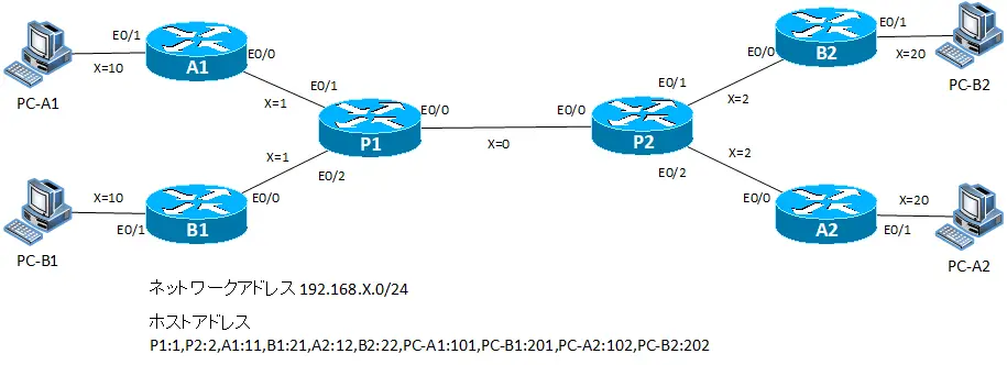
ネットワーク構成
設定条件
- A社のPC-A1とPC-A2の通信ができるようにレイヤ3VPNを構築します。また、B社のPC-B1とPC-B2の通信ができるようにレイヤ3VPNを構築します。
- P1/P2で設定するVRF名とRDは以下の通りです。
| ルータ | VRF名 | RD | インタフェース |
|---|---|---|---|
| P1 | VRF-A | 10:10 | E0/1 E0/0.10 Lo1 |
| VRF-B | 20:20 | E0/2 E0/0.20 Lo2 | |
| P2 | VRF-A | 10:10 | E0/2 E0/0.10 Lo1 |
| VRF-B | 20:20 | E0/1 E0/0.20 Lo2 |
- P1、P2のLo1とLo2のIPアドレスはLo0と同じアドレスを設定します。
- ルーティングの設定を以下の表のように行います。
| VRF | ルータ | ルーティングプロトコル |
|---|---|---|
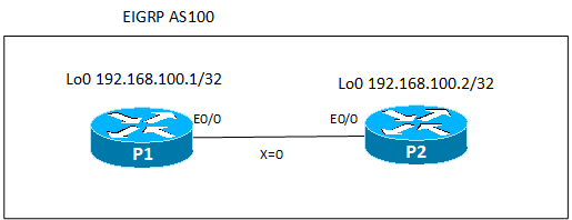
| グローバル | P1-P2 | EIGRP AS100 |
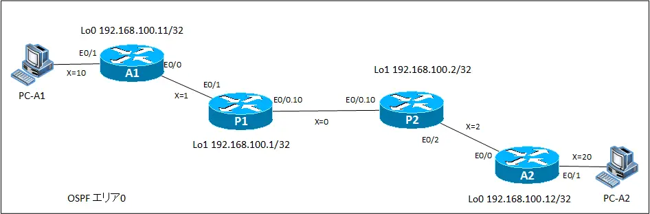
| VRF-A | A1-P1,P1-P2,A2-P2 | OSPFエリア0 |
| VRF-B | B1-P1,P1-P2,P2-B2 | EIGRP AS20 |
初期設定
初期設定として、ホスト名やIPアドレスを設定している状態から開始します。P1/P2はグローバルルーティングプロセスのIPアドレスのみの設定です。各機器の初期設定の抜粋は以下の通りです。
P1 設定抜粋(Click)
hostname P1
!
interface Loopback0
 ip address 192.168.100.1 255.255.255.255
!
interface Ethernet0/0
 ip address 192.168.0.1 255.255.255.0
P2 設定抜粋(Click)
hostname P2
!
interface Loopback0
 ip address 192.168.100.2 255.255.255.255
!
interface Ethernet0/0
 ip address 192.168.0.2 255.255.255.0
A1 設定抜粋(Click)
hostname A1
!
interface Loopback0
 ip address 192.168.100.11 255.255.255.255
!
interface Ethernet0/0
 ip address 192.168.1.11 255.255.255.0
!
interface Ethernet0/1
 ip address 192.168.10.11 255.255.255.0
A2 設定抜粋(Click)
hostname A2
!
interface Loopback0
 ip address 192.168.100.12 255.255.255.0
!
interface Ethernet0/0
 ip address 192.168.2.12 255.255.255.0
!
interface Ethernet0/1
 ip address 192.168.20.12 255.255.255.0
B1 設定抜粋(Click)
hostname B1
!
interface Loopback0
 ip address 192.168.100.21 255.255.255.255
!
interface Ethernet0/0
 ip address 192.168.1.21 255.255.255.0
!
interface Ethernet0/1
 ip address 192.168.10.21 255.255.255.0
B2 設定抜粋(Click)
hostname B2
!
interface Loopback0
 ip address 192.168.100.22 255.255.255.255
!
interface Ethernet0/0
 ip address 192.168.2.22 255.255.255.0
!
interface Ethernet0/1
 ip address 192.168.20.22 255.255.255.0
PC-A1 設定抜粋(Click)
hostname PC-A1
!
no ip routing
!
interface Ethernet0/0
 ip address 192.168.10.101 255.255.255.0
!
ip default-gateway 192.168.10.11
PC-A2 設定抜粋(Click)
hostname PC-A2
!
no ip routing
!
interface Ethernet0/0
 ip address 192.168.20.102 255.255.255.0
!
ip default-gateway 192.168.20.12
PC-B1 設定抜粋(Click)
hostname PC-B1
!
no ip routing
!
interface Ethernet0/0
 ip address 192.168.10.201 255.255.255.0
!
ip default-gateway 192.168.10.21
PC-B2 設定抜粋(Click)
hostname PC-B2
!
no ip routing
!
interface Ethernet0/0
 ip address 192.168.20.202 255.255.255.0
!
ip default-gateway 192.168.20.22
設定と確認
Step1:VRFの設定
表 VRFの設定に基づいて、P1とP2でVRFを作成しインタフェースを割り当てます。P1-P2間はそれぞれのVRF用にサブインタフェースを作成してVRFの割り当てとIPアドレスの設定を行います。
P1 VRFの設定
ip vrf VRF-A
 rd 10:10
!
ip vrf VRF-B
 rd 20:20
!
interface Loopback1
 ip vrf forwarding VRF-A
 ip address 192.168.100.1 255.255.255.255
!
interface Loopback2
 ip vrf forwarding VRF-B
 ip address 192.168.100.1 255.255.255.255
!
interface Ethernet0/0.10
 encapsulation dot1Q 10
 ip vrf forwarding VRF-A
 ip address 192.168.0.1 255.255.255.0
!
interface Ethernet0/0.20
 encapsulation dot1Q 20
 ip vrf forwarding VRF-B
 ip address 192.168.0.1 255.255.255.0
!
interface Ethernet0/1
 ip vrf forwarding VRF-A
 ip address 192.168.1.1 255.255.255.0
!
interface Ethernet0/2
 ip vrf forwarding VRF-B
 ip address 192.168.1.1 255.255.255.0
P2 VRFの設定
ip vrf VRF-A
 rd 10:10
!
ip vrf VRF-B
 rd 20:20
!
interface Loopback1
 ip vrf forwarding VRF-A
 ip address 192.168.100.2 255.255.255.255
!
interface Loopback2
 ip vrf forwarding VRF-B
 ip address 192.168.100.2 255.255.255.255
!
interface Ethernet0/0.10
 encapsulation dot1Q 10
 ip vrf forwarding VRF-A
 ip address 192.168.0.2 255.255.255.0
!
interface Ethernet0/0.20
 encapsulation dot1Q 20
 ip vrf forwarding VRF-B
 ip address 192.168.0.2 255.255.255.0
!
interface Ethernet0/1
 ip vrf forwarding VRF-B
 ip address 192.168.2.2 255.255.255.0
!
interface Ethernet0/2
 ip vrf forwarding VRF-A
 ip address 192.168.2.2 255.255.255.0
Step2:VRFの確認
P1およびP2でshow ip vrfコマンドでVRFの状態を確認します。また、グローバルルーティングテーブルとVRFのルーティングテーブルを確認します。P1では、以下のような表示になります。
P1 VRFの確認
P1#show ip vrf
Name Default RD Interfaces
VRF-A 10:10 Et0/1
Lo1
Et0/0.10
VRF-B 20:20 Et0/2
Lo2
Et0/0.20
P1#show ip vrf detail
VRF VRF-A; default RD 10:10; default VPNID
Step3:グローバルルーティングプロセスのルーティングの設定
P1とP2でEIGRPによってグローバルルーティングプロセスのルーティングを行います。
P1/P2 グローバルルーティングプロセスのルーティング
router eigrp 100
 network 192.168.0.0 0.0.255.255
 no auto-summary
Step4:グローバルルーティングプロセスのルーティングの確認
P1とP2でグローバルルーティングプロセスのルーティングを確認します。
- show ip eigrp neighbor
- show ip route
P1では、以下のような出力結果です。
P1 グローバルルーティングプロセスのルーティングの確認
P1#show ip eigrp neighbors
IP-EIGRP neighbors for process 100
H   Address                 Interface       Hold Uptime   SRTT   RTO  Q  Seq
                                            (sec)         (ms)       Cnt Num
0   192.168.0.2             Et0/0             12 00:01:29   17   200  0  3
P1#show ip route
Codes: C - connected, S - static, R - RIP, M - mobile, B - BGP
       D - EIGRP, EX - EIGRP external, O - OSPF, IA - OSPF inter area
       N1 - OSPF NSSA external type 1, N2 - OSPF NSSA external type 2
       E1 - OSPF external type 1, E2 - OSPF external type 2
       i - IS-IS, su - IS-IS summary, L1 - IS-IS level-1, L2 - IS-IS level-2
       ia - IS-IS inter area, * - candidate default, U - per-user static route
       o - ODR, P - periodic downloaded static route

Gateway of last resort is not set

C    192.168.0.0/24 is directly connected, Ethernet0/0
     192.168.100.0/32 is subnetted, 2 subnets
C       192.168.100.1 is directly connected, Loopback0
D       192.168.100.2 [90/409600] via 192.168.0.2, 00:01:30, Ethernet0/0
P1#ping 192.168.100.2 source loopback 0

Type escape sequence to abort.
Sending 5, 100-byte ICMP Echos to 192.168.100.2, timeout is 2 seconds:
Packet sent with a source address of 192.168.100.1
!!!!!
Success rate is 100 percent (5/5), round-trip min/avg/max = 12/19/24 ms
グローバルルーティングプロセスのルーティングは以下のような構成です。
Step5:VRF-Aのルーティングの設定
VRF-Aのルーティングの設定を行います。OSPFエリア0のシングルエリア構成でルーティングを行います。OSPFでは、ルーティングプロセスを有効にするときにVRFを指定します。
P1/P2 VRF-A ルーティングの設定
router ospf 1 vrf VRF-A
 network 192.168.0.0 0.0.255.255 area 0
A1/A2 ルーティングの設定
router ospf 1
 network 192.168.0.0 0.0.255.255 area 0
Step6:VRF-Aのルーティングの確認
P1とP2でVRF-Aのルーティングを確認します。
- show ip ospf neighbor
- show ip route vrf VRF-A
- ping vrf VRF-A
P1では次のような出力です。
P1 VRF-Aのルーティングの確認
P1#show ip ospf neighbor

Neighbor ID     Pri   State           Dead Time   Address         Interface
192.168.100.11    1   FULL/DR         00:00:35    192.168.1.11    Ethernet0/1
192.168.100.2     1   FULL/DR         00:00:35    192.168.0.2     Ethernet0/0.10
P1#show ip route vrf VRF-A

Routing Table: VRF-A
Codes: C - connected, S - static, R - RIP, M - mobile, B - BGP
       D - EIGRP, EX - EIGRP external, O - OSPF, IA - OSPF inter area
       N1 - OSPF NSSA external type 1, N2 - OSPF NSSA external type 2
       E1 - OSPF external type 1, E2 - OSPF external type 2
       i - IS-IS, su - IS-IS summary, L1 - IS-IS level-1, L2 - IS-IS level-2
       ia - IS-IS inter area, * - candidate default, U - per-user static route
       o - ODR, P - periodic downloaded static route

Gateway of last resort is not set

O    192.168.10.0/24 [110/20] via 192.168.1.11, 00:04:40, Ethernet0/1
O    192.168.20.0/24 [110/30] via 192.168.0.2, 00:04:40, Ethernet0/0.10
C    192.168.0.0/24 is directly connected, Ethernet0/0.10
C    192.168.1.0/24 is directly connected, Ethernet0/1
O    192.168.2.0/24 [110/20] via 192.168.0.2, 00:04:40, Ethernet0/0.10
     192.168.100.0/32 is subnetted, 4 subnets
O       192.168.100.12 [110/21] via 192.168.0.2, 00:04:40, Ethernet0/0.10
O       192.168.100.11 [110/11] via 192.168.1.11, 00:04:41, Ethernet0/1
C       192.168.100.1 is directly connected, Loopback1
O       192.168.100.2 [110/11] via 192.168.0.2, 00:04:41, Ethernet0/0.10
P1#ping vrf VRF-A 192.168.10.101 source loopback 1

Type escape sequence to abort.
Sending 5, 100-byte ICMP Echos to 192.168.10.101, timeout is 2 seconds:
Packet sent with a source address of 192.168.100.1
!!!!!
Success rate is 100 percent (5/5), round-trip min/avg/max = 20/29/40 ms
P1#ping vrf VRF-A 192.168.20.102 source loopback 1

Type escape sequence to abort.
Sending 5, 100-byte ICMP Echos to 192.168.20.102, timeout is 2 seconds:
Packet sent with a source address of 192.168.100.1
!!!!!
Success rate is 100 percent (5/5), round-trip min/avg/max = 40/48/64 ms
VRF-Aのルーティングの構成は以下のようになります。
これでVRF-Aによって、A社のみの通信ができるA社用のVPNの設定と確認は完了です。
Step7:VRF-Bのルーティングの設定
VRF-Bのルーティングの設定を行います。EIGRP AS20の設定を行います。EIGRPでは、address-familyとしてVRFを指定します。
P1/P2 VRF-Bのルーティングの設定
router eigrp 100
 address-family ipv4 vrf VRF-B
  autonomous-system 20
  network 192.168.0.0 0.0.255.255
  no auto-summary
VRF用のEIGRPのAS番号の指定は、以下のように設定することもできます。
router eigrp 100
address-family ipv4 vrf VRF-B autonomous-system 20
B1/B2 ルーティングの設定
router eigrp 20
 network 192.168.0.0 0.0.255.255
 no auto-summary
Step8:VRF-Bのルーティングの確認
P1とP2でVRF-Bのルーティングを確認します。
- show ip eigrp vrf VRF-B neighbor
- show ip route vrf VRF-B
- ping vrf VRF-B
P1では次のような出力です。
P1 VRF-Bのルーティングの確認
P1#show ip eigrp vrf VRF-B neighbors
IP-EIGRP neighbors for process 20
H   Address                 Interface       Hold Uptime   SRTT   RTO  Q  Seq
                                            (sec)         (ms)       Cnt Num
1   192.168.1.21            Et0/2             10 00:00:23   16   200  0  3
0   192.168.0.2             Et0/0.20          13 00:01:33   21   200  0  12
P1#show ip route vrf VRF-B

Routing Table: VRF-B
Codes: C - connected, S - static, R - RIP, M - mobile, B - BGP
       D - EIGRP, EX - EIGRP external, O - OSPF, IA - OSPF inter area
       N1 - OSPF NSSA external type 1, N2 - OSPF NSSA external type 2
       E1 - OSPF external type 1, E2 - OSPF external type 2
       i - IS-IS, su - IS-IS summary, L1 - IS-IS level-1, L2 - IS-IS level-2
       ia - IS-IS inter area, * - candidate default, U - per-user static route
       o - ODR, P - periodic downloaded static route

Gateway of last resort is not set

D    192.168.10.0/24 [90/307200] via 192.168.1.21, 00:00:35, Ethernet0/2
D    192.168.20.0/24 [90/332800] via 192.168.0.2, 00:00:22, Ethernet0/0.20
C    192.168.0.0/24 is directly connected, Ethernet0/0.20
C    192.168.1.0/24 is directly connected, Ethernet0/2
D    192.168.2.0/24 [90/307200] via 192.168.0.2, 00:00:26, Ethernet0/0.20
     192.168.100.0/32 is subnetted, 4 subnets
C       192.168.100.1 is directly connected, Loopback2
D       192.168.100.2 [90/409600] via 192.168.0.2, 00:01:46, Ethernet0/0.20
D       192.168.100.21 [90/409600] via 192.168.1.21, 00:00:36, Ethernet0/2
D       192.168.100.22 [90/435200] via 192.168.0.2, 00:00:24, Ethernet0/0.20
P1#ping vrf VRF-B 192.168.10.201 source loopback 2

Type escape sequence to abort.
Sending 5, 100-byte ICMP Echos to 192.168.10.201, timeout is 2 seconds:
Packet sent with a source address of 192.168.100.1
!!!!!
Success rate is 100 percent (5/5), round-trip min/avg/max = 20/37/48 ms
P1#ping vrf VRF-B 192.168.20.202 source loopback 2

Type escape sequence to abort.
Sending 5, 100-byte ICMP Echos to 192.168.20.202, timeout is 2 seconds:
Packet sent with a source address of 192.168.100.1
!!!!!
Success rate is 100 percent (5/5), round-trip min/avg/max = 24/39/44 ms
VRF-Bのルーティングの構成は以下のようになります。
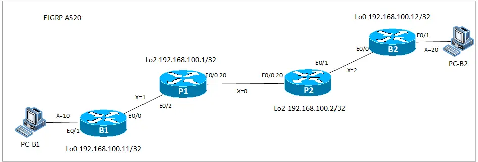
これでB社用のVPNの設定と確認は完了です。A社とB社では、アドレス範囲が重複しています。でも、P1/P2でVRFによって分離しているので、A社とB社のアドレス範囲が重複していても問題ありません。

IPルーティング応用
- DNSラウンドロビン方式の負荷分散
- 負荷分散装置(ロードバランサ)の仕組み
- ルーティングプロセス ~実行中のルーティングプロトコル用のプログラム~
- 複数のルーティングプロトコルの利用
- 再配送(再配布) ~ルーティングドメイン境界で必須の設定~
- Cisco再配送(再配布)の設定 ~redistributeコマンド~
- Cisco 再配送の設定例 ~OSPFとRIPの双方向再配送~
- 再配送 設定ミスの切り分けと修正 Part1
- 再配送 設定ミスの切り分けと修正 Part2
- 再配送 設定ミスの切り分けと修正 Part3
- 再配送 設定ミスの切り分けと修正 Part4
- 再配送 設定ミスの切り分けと修正 Part5
- 再配送 設定ミスの切り分けと修正 Part6
- オフセットリスト(offset-list) ~ルート情報のメトリックを加算~
- オフセットリストの設定例 RIP
- オフセットリストの設定例 EIGRP
- ルートフィルタの概要
- ルートフィルタのポイント
- ディストリビュートリストによるルートフィルタの設定
- Ciscoディストリビュートリストによるルートフィルタの設定例
- プレフィクスリスト(prefix-list)によるルートフィルタの設定
- Ciscoプレフィクスリストによるルートフィルタの設定例
- Ciscoルートマップ(route-map)の概要 ~何をどう処理するか~
- Ciscoルートマップの設定
- Ciscoルートマップ(route-map)設定のポイント
- Ciscoルートマップによる再配送時のルート制御の設定例
- ポリシーベースルーティングの設定例
- GREトンネルインタフェース ~仮想的なポイントツーポイント接続~
- GREトンネルインタフェースの設定例
- GREトンネルの注意点 ~フラッピングしないように~
- オーバーレイネットワークとアンダーレイネットワーク
- ルート制御 ケーススタディ Part1
- ルート制御 ケーススタディ Part2
- ルート制御 ケーススタディ Part3
- VRF/VRF-Liteの概要 ~仮想的にルータを分割する~
- VRFの設定と確認コマンド [Cisco]
- VRF-Liteによるレイヤ3VPNの設定例 [Cisco]
- VRFルートリーク(スタティックルート)
- VRFルートリーク(スタティックルート)の設定例
- VRFルートリーク(MP-BGP)
- VRFルートリーク(MP-BGP)の設定例
- [FVRFの仕組み] FVRF(Front door VRF)とは
- [FVRFの仕組み] ポイントツーポイントGREトンネル:FVRFなし
- [FVRFの仕組み] ポイントツーポイントGREトンネル : FVRFあり(tunnel vrfコマンド)
- [FVRFの仕組み] IPSec VTI : FRVRFあり
- [FVRFの仕組み] IPSec VTI : FVRFあり 設定例
- [FVRFの仕組み] DMVPN : FVRFあり
- [FVRFの仕組み] DMVPN : FVRFあり 設定例 Part1
- [FVRFの仕組み] DMVPN : FVRFあり 設定例 Part2
- tunnel vrfコマンド
- tunnel vrfコマンドの設定例
- [演習] ルーティングループの防止
- [演習] 企業ネットワーク構築演習 Part1:拠点1の構築
- [演習] 企業ネットワーク構築演習 Part2:拠点2/拠点3の構築
- [演習] 企業ネットワーク構築演習 Part3:広域イーサネットの接続
- [演習] 企業ネットワーク構築演習 Part4:インターネット(AS1/AS2)の構築
- [演習] 企業ネットワーク構築演習 Part5:インターネットへの接続
- [演習] 企業ネットワーク構築演習 Part6:インターネットVPNの構築
