目次
概要
MP-BGPによるVRFルートリークによって、異なるVRF間で通信できるようにする設定例です。それぞれの設定の意味がわかりやすくなるように、手順を細かく区切って設定していきます。
関連記事
CiscoでのVRFの設定と確認コマンドは以下の記事で解説しています。
MP-BGPによるVRFルートリークの仕組みについて、以下の記事で解説しています。
ネットワーク構成

設定条件
- VRF「AAA」の192.168.1.0/24とVRF「BBB」の172.16.1.0/24間でのみ通信できるようにします。
- MP-BGPによるVRFルートリークの設定を行います。

初期設定
R1でVRF「AAA」とVRF「BBB」を作成しています。RD、Import RT/Export RTおよび割り当てているインタフェースは次のようになります。
| VRF名 | RD | Import RT | Export RT | インタフェース |
| AAA | 1:100 | 1:100 | 1:100 | Fa0/0 |
| BBB | 2:100 | 2:100 | 2:100 | Fa0/1 |
また、VRF「AAA」内のルーティングができるようにR1/R2でOSPFの設定を行っています。同様にVRF「BBB」内でルーティングできるようにR1/R3でEIGRPの設定も行っています。
R1 初期設定抜粋(Click)
hostname R1
!
ip vrf AAA
 rd 1:100
 route-target export 1:100
 route-target import 1:100
!
ip vrf BBB
 rd 2:100
 route-target export 2:100
 route-target import 2:100
!
interface FastEthernet0/0
 ip vrf forwarding AAA
 ip address 192.168.0.1 255.255.255.0
!
interface FastEthernet0/1
 ip vrf forwarding BBB
 ip address 172.16.0.1 255.255.255.0
!
router eigrp 1
 auto-summary
 !
 address-family ipv4 vrf BBB
  network 172.16.0.0
  no auto-summary
  autonomous-system 1
 exit-address-family
 eigrp router-id 1.1.1.1
!
router ospf 1 vrf AAA
 router-id 1.1.1.1
 log-adjacency-changes
 network 192.168.0.0 0.0.255.255 area 0
R2 初期設定抜粋(Click)
hostname R2
!
interface Loopback1
 ip address 192.168.1.2 255.255.255.0
!
interface Loopback2
 ip address 192.168.2.2 255.255.255.0
!
interface FastEthernet0/0
 ip address 192.168.0.2 255.255.255.0
!
router ospf 1
 router-id 2.2.2.2
 log-adjacency-changes
 network 192.168.0.0 0.0.255.255 area 0
R3 初期設定抜粋(Click)
hostname R3
!
interface Loopback1
 ip address 172.16.1.3 255.255.255.0
!
interface Loopback2
 ip address 172.16.2.3 255.255.255.0
!
interface FastEthernet0/0
 ip address 172.16.0.3 255.255.255.0
!
router eigrp 1
 network 172.16.0.0
 no auto-summary
 eigrp router-id 3.3.3.3
設定と確認
Step1:VRF間の通信の確認
VRFルートリークの設定を行っていない状態でVRF間の通信を確認します。R2からR3へPingを実行します。
R2 VRF間の通信の確認
R2#ping 172.16.1.3 source loopback 1

Type escape sequence to abort.
Sending 5, 100-byte ICMP Echos to 172.16.1.3, timeout is 2 seconds:
Packet sent with a source address of 192.168.1.2
.....
Success rate is 0 percent (0/5)
R2#ping 172.16.1.3 source loopback 2

Type escape sequence to abort.
Sending 5, 100-byte ICMP Echos to 172.16.1.3, timeout is 2 seconds:
Packet sent with a source address of 192.168.2.2
.....
Success rate is 0 percent (0/5)
R2#ping 172.16.2.3 source loopback 1

Type escape sequence to abort.
Sending 5, 100-byte ICMP Echos to 172.16.2.3, timeout is 2 seconds:
Packet sent with a source address of 192.168.1.2
.....
Success rate is 0 percent (0/5)
R2#ping 172.16.2.3 source loopback 2

Type escape sequence to abort.
Sending 5, 100-byte ICMP Echos to 172.16.2.3, timeout is 2 seconds:
Packet sent with a source address of 192.168.2.2
.....
Success rate is 0 percent (0/5)
VRF「AAA」とVRF「BBB」間の通信はできないことがわかります。
Step2:VRF「AAA」のルートをVPNv4ルートとして生成
VRF「AAA」のルートをVPNv4ルートとしてMP-BGPテーブルに生成します。R1のVRF「AAA」において、OSPFからBGPへ再配送します。
R1 VPNv4ルートの生成(VRF「AAA」)
router bgp 65001
 bgp router-id 1.1.1.1
!
 address-family ipv4 vrf AAA
  redistribute ospf 1 vrf AAA
Step3:VPNv4ルートの確認
Step2で生成したVPNv4ルートを確認します。R1でshow bgp vpnv4 unicast allコマンドを利用します。
R1 VPNv4ルートの確認
R1#show bgp vpnv4 unicast all
BGP table version is 7, local router ID is 1.1.1.1
Status codes: s suppressed, d damped, h history, * valid, > best, i - internal,
              r RIB-failure, S Stale
Origin codes: i - IGP, e - EGP, ? - incomplete

   Network          Next Hop            Metric LocPrf Weight Path
Route Distinguisher: 1:100 (default for vrf AAA)
*> 192.168.0.0      0.0.0.0                  0         32768 ?
*> 192.168.1.0      192.168.0.2             11         32768 ?
*> 192.168.2.0      192.168.0.2             11         32768 ?
R1#show bgp vpnv4 unicast all 192.168.1.0
BGP routing table entry for 1:100:192.168.1.0/24, version 4
Paths: (1 available, best #1, table AAA)
Flag: 0x820
  Not advertised to any peer
  Local
    192.168.0.2 from 0.0.0.0 (1.1.1.1)
      Origin incomplete, metric 11, localpref 100, weight 32768, valid, sourced, best
      Extended Community: RT:1:100 OSPF DOMAIN ID:0x0005:0x000000010200
        OSPF RT:0.0.0.0:2:0 OSPF ROUTER ID:1.1.1.1:0
      mpls labels in/out 17/nolabel
VPNv4ルートには、Export RT「1:100」が付加されています。
Step4:VRF「BBB」へのルートリークの設定
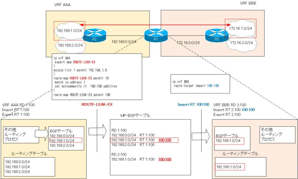
条件に基づいてVRF「AAA」の「192.168.1.0/24」のルートをVRF「BBB」のルーティングテーブルに登録します。リークするルート「192.168.1.0/24」に追加でRT「100:100」を付加します。特定のルートに追加でRTを付加するためにVRF「AAA」内でexport mapでルートマップを関連付けます。
R1 リークするルートに追加のRTを付加
ip vrf AAA
 export map ROUTE-LEAK-EX
!
access-list 1 permit 192.168.1.0
!
route-map ROUTE-LEAK-EX permit 10
 match ip address 1
 set extcommunity rt  100:100 additive
!
route-map ROUTE-LEAK-EX permit 100
そして、リーク先のVRF「BBB」でリークするルート「192.168.1.0/24」に付加したRT「100:100」を受け入れるようにImport RTを追加します。
R1 VRF「BBB」 Import RTを追加
ip vrf BBB
 route-target import 100:100
Step5:VRF「BBB」へのルートリークの確認
VRF「AAA」の「192.168.1.0/24」がVRF「BBB」へリークされていることを確認します。
R1 VRF「BBB」へのルートリークの確認
R1#show ip vrf detail BBB VRF BBB; default RD 2:100; default VPNIDInterfaces: Fa0/1 Connected addresses are not in global routing table Export VPN route-target communities RT:2:100 Import VPN route-target communities RT:2:100 RT:100:100 No import route-map No export route-map VRF label distribution protocol: not configured VRF label allocation mode: per-prefix R1#show bgp vpnv4 unicast all BGP table version is 9, local router ID is 1.1.1.1 Status codes: s suppressed, d damped, h history, * valid, > best, i - internal, r RIB-failure, S Stale Origin codes: i - IGP, e - EGP, ? - incomplete Network Next Hop Metric LocPrf Weight Path Route Distinguisher: 1:100 (default for vrf AAA) *> 192.168.0.0 0.0.0.0 0 32768 ? *> 192.168.1.0 192.168.0.2 11 32768 ? *> 192.168.2.0 192.168.0.2 11 32768 ? Route Distinguisher: 2:100 (default for vrf BBB) *> 192.168.1.0 192.168.0.2 11 32768 ? R1#show bgp vpnv4 unicast vrf BBB 192.168.1.0 BGP routing table entry for 2:100:192.168.1.0/24, version 9 Paths: (1 available, best #1, table BBB) Not advertised to any peer Local, imported path from 1:100:192.168.1.0/24 192.168.0.2 from 0.0.0.0 (1.1.1.1) Origin incomplete, metric 11, localpref 100, weight 32768, valid, external, best Extended Community: RT:1:100 RT:100:100 OSPF DOMAIN ID:0x0005:0x000000010200 OSPF RT:0.0.0.0:2:0 OSPF ROUTER ID:1.1.1.1:0 R1#show ip route vrf BBB Routing Table: BBB Codes: C - connected, S - static, R - RIP, M - mobile, B - BGP D - EIGRP, EX - EIGRP external, O - OSPF, IA - OSPF inter area N1 - OSPF NSSA external type 1, N2 - OSPF NSSA external type 2 E1 - OSPF external type 1, E2 - OSPF external type 2 i - IS-IS, su - IS-IS summary, L1 - IS-IS level-1, L2 - IS-IS level-2 ia - IS-IS inter area, * - candidate default, U - per-user static route o - ODR, P - periodic downloaded static route Gateway of last resort is not set 172.16.0.0/24 is subnetted, 3 subnets C 172.16.0.0 is directly connected, FastEthernet0/1 D 172.16.1.0 [90/409600] via 172.16.0.3, 00:21:11, FastEthernet0/1 D 172.16.2.0 [90/409600] via 172.16.0.3, 00:21:11, FastEthernet0/1 B 192.168.1.0/24 [20/11] via 192.168.0.2 (AAA), 00:08:46, FastEthernet0/0
VRF「AAA」の「192.168.1.0/24」がVRF「BBB」へリークされています。VRF「BBB」では、BGPルートとして「192.168.1.0/24」がルーティングテーブルに登録されます。
以下の図は、Step2~Step5の設定によってVRF「AAA」のルート「192.168.1.0/24」がVRF「BBB」にリークされる様子を表しています。

あとは、この逆方向、すなわち、VRF「BBB」の「172.16.1.0/24」をVRF「AAA」にリークすればOKです。考え方は同じです。
Step6:VRF「BBB」の「172.16.1.0/24」をVRF「AAA」へリークする設定
考え方は同じなので、逆方向の設定はまとめて行います。なお、追加のRTを付加するためのルートマップ「ROUTE-LEAK-EX」は使い回せます。対象のネットワークアドレスを指定するACL1に172.16.1.0/24をpermitする条件を追加すればいいだけです。
R1 VRF「BBB」の「172.16.1.0/24」をVRF「AAA」へリーク
ip vrf AAA
 route-target import 100:100
!
ip vrf BBB
 export map ROUTE-LEAK-EX
!
router bgp 65001
address-family ipv4 vrf BBB
  redistribute eigrp 1
!
access-list 1 permit 172.16.1.0
Step7:VRF「BBB」の「172.16.1.0/24」をVRF「AAA」へリークする確認
VRF「BBB」の「172.16.1.0/24」をVRF「AAA」にリークされていることを確認します。
R1 VRF「AAA」へのルートリークの確認
R1#show bgp vpnv4 unicast vrf AAA
BGP table version is 17, local router ID is 1.1.1.1
Status codes: s suppressed, d damped, h history, * valid, > best, i - internal,
              r RIB-failure, S Stale
Origin codes: i - IGP, e - EGP, ? - incomplete

   Network          Next Hop            Metric LocPrf Weight Path
Route Distinguisher: 1:100 (default for vrf AAA)
*> 172.16.1.0/24    172.16.0.3          409600         32768 ?
*> 192.168.0.0      0.0.0.0                  0         32768 ?
*> 192.168.1.0      192.168.0.2             11         32768 ?
*> 192.168.2.0      192.168.0.2             11         32768 ?
R1#show ip route vrf AAA

Routing Table: AAA
Codes: C - connected, S - static, R - RIP, M - mobile, B - BGP
       D - EIGRP, EX - EIGRP external, O - OSPF, IA - OSPF inter area
       N1 - OSPF NSSA external type 1, N2 - OSPF NSSA external type 2
       E1 - OSPF external type 1, E2 - OSPF external type 2
       i - IS-IS, su - IS-IS summary, L1 - IS-IS level-1, L2 - IS-IS level-2
       ia - IS-IS inter area, * - candidate default, U - per-user static route
       o - ODR, P - periodic downloaded static route

Gateway of last resort is not set

     172.16.0.0/24 is subnetted, 1 subnets
B       172.16.1.0 [20/409600] via 172.16.0.3 (BBB), 00:06:12, FastEthernet0/1
C    192.168.0.0/24 is directly connected, FastEthernet0/0
O    192.168.1.0/24 [110/11] via 192.168.0.2, 00:45:07, FastEthernet0/0
O    192.168.2.0/24 [110/11] via 192.168.0.2, 00:45:07, FastEthernet0/0
VRF「AAA」のルーティングテーブルにVRF「BBB」の「172.16.1.0/24」が登録されています。
Step8:VRF間の通信の確認
R1でVRFルートリークの設定が完了したので、VRF間の通信を確認します。R2からR3へPingします。
R2 VRF間の通信の確認
R2#ping 172.16.1.3 source loopback 1

Type escape sequence to abort.
Sending 5, 100-byte ICMP Echos to 172.16.1.3, timeout is 2 seconds:
Packet sent with a source address of 192.168.1.2
.....
Success rate is 0 percent (0/5)
———————-
まだ、VRF間で「192.168.1.0/24」と「172.16.1.0/24」の間の通信はできません。R1でリークした他のVRFのルートはBGPルートです。ルートリークしただけでは、R2やR3にはルートがアドバタイズされていません。この時点でのR2/R3のルーティングテーブルは以下の通りです。
R2
R2#show ip route
Codes: C - connected, S - static, R - RIP, M - mobile, B - BGP
       D - EIGRP, EX - EIGRP external, O - OSPF, IA - OSPF inter area
       N1 - OSPF NSSA external type 1, N2 - OSPF NSSA external type 2
       E1 - OSPF external type 1, E2 - OSPF external type 2
       i - IS-IS, su - IS-IS summary, L1 - IS-IS level-1, L2 - IS-IS level-2
       ia - IS-IS inter area, * - candidate default, U - per-user static route
       o - ODR, P - periodic downloaded static route

Gateway of last resort is not set

C    192.168.0.0/24 is directly connected, FastEthernet0/0
C    192.168.1.0/24 is directly connected, Loopback1
C    192.168.2.0/24 is directly connected, Loopback2
R3
R3#show ip route
Codes: C - connected, S - static, R - RIP, M - mobile, B - BGP
       D - EIGRP, EX - EIGRP external, O - OSPF, IA - OSPF inter area
       N1 - OSPF NSSA external type 1, N2 - OSPF NSSA external type 2
       E1 - OSPF external type 1, E2 - OSPF external type 2
       i - IS-IS, su - IS-IS summary, L1 - IS-IS level-1, L2 - IS-IS level-2
       ia - IS-IS inter area, * - candidate default, U - per-user static route
       o - ODR, P - periodic downloaded static route

Gateway of last resort is not set

     172.16.0.0/24 is subnetted, 3 subnets
C       172.16.0.0 is directly connected, FastEthernet0/0
C       172.16.1.0 is directly connected, Loopback1
C       172.16.2.0 is directly connected, Loopback2
R1でリークした他のVRFのルートを、それぞれのVRFで利用しているルーティングプロトコルでアドバタイズしなければいけません。
Step9:リークしたルートをVRF内でアドバタイズ
R1でリークした他のVRFのルートをVRF内のルーティングプロトコルでアドバタイズします。リークした他のVRFルートはBGPルートです。そのため、BGPからVRF内のルーティングプロトコルへ再配送します。
R1 リークしたルートをVRF内でアドバタイズ
router eigrp 1
address-family ipv4 vrf BBB
  redistribute bgp 65001 metric 100000 100 255 1 1500
!
router ospf 1 vrf AAA
 redistribute bgp 65001 subnets
これで条件通りVRF「AAA」の「192.168.1.0/24」とVRF「BBB」の「172.16.1.0/24」間の通信を行うための設定はすべて完了です。
Step10:VRF間の通信の確認
R1/R2/R3のルーティングテーブルを確認します。
R1 ルーティングテーブル
R1#show ip route vrf AAA

Routing Table: AAA
Codes: C - connected, S - static, R - RIP, M - mobile, B - BGP
       D - EIGRP, EX - EIGRP external, O - OSPF, IA - OSPF inter area
       N1 - OSPF NSSA external type 1, N2 - OSPF NSSA external type 2
       E1 - OSPF external type 1, E2 - OSPF external type 2
       i - IS-IS, su - IS-IS summary, L1 - IS-IS level-1, L2 - IS-IS level-2
       ia - IS-IS inter area, * - candidate default, U - per-user static route
       o - ODR, P - periodic downloaded static route

Gateway of last resort is not set

     172.16.0.0/24 is subnetted, 1 subnets
B       172.16.1.0 [20/409600] via 172.16.0.3 (BBB), 00:27:03, FastEthernet0/1
C    192.168.0.0/24 is directly connected, FastEthernet0/0
O    192.168.1.0/24 [110/11] via 192.168.0.2, 01:05:58, FastEthernet0/0
O    192.168.2.0/24 [110/11] via 192.168.0.2, 01:05:58, FastEthernet0/0
R1#show ip route vrf BBB

Routing Table: BBB
Codes: C - connected, S - static, R - RIP, M - mobile, B - BGP
       D - EIGRP, EX - EIGRP external, O - OSPF, IA - OSPF inter area
       N1 - OSPF NSSA external type 1, N2 - OSPF NSSA external type 2
       E1 - OSPF external type 1, E2 - OSPF external type 2
       i - IS-IS, su - IS-IS summary, L1 - IS-IS level-1, L2 - IS-IS level-2
       ia - IS-IS inter area, * - candidate default, U - per-user static route
       o - ODR, P - periodic downloaded static route

Gateway of last resort is not set

     172.16.0.0/24 is subnetted, 3 subnets
C       172.16.0.0 is directly connected, FastEthernet0/1
D       172.16.1.0 [90/409600] via 172.16.0.3, 01:06:32, FastEthernet0/1
D       172.16.2.0 [90/409600] via 172.16.0.3, 01:06:32, FastEthernet0/1
B    192.168.1.0/24 [20/11] via 192.168.0.2 (AAA), 00:54:08, FastEthernet0/0
R2 ルーティングテーブル
R2#show ip route
Codes: C - connected, S - static, R - RIP, M - mobile, B - BGP
       D - EIGRP, EX - EIGRP external, O - OSPF, IA - OSPF inter area
       N1 - OSPF NSSA external type 1, N2 - OSPF NSSA external type 2
       E1 - OSPF external type 1, E2 - OSPF external type 2
       i - IS-IS, su - IS-IS summary, L1 - IS-IS level-1, L2 - IS-IS level-2
       ia - IS-IS inter area, * - candidate default, U - per-user static route
       o - ODR, P - periodic downloaded static route

Gateway of last resort is not set

     172.16.0.0/24 is subnetted, 1 subnets
O E2    172.16.1.0 [110/409600] via 192.168.0.1, 00:03:16, FastEthernet0/0
C    192.168.0.0/24 is directly connected, FastEthernet0/0
C    192.168.1.0/24 is directly connected, Loopback1
C    192.168.2.0/24 is directly connected, Loopback2
R3 ルーティングテーブル
R3#show ip route
Codes: C - connected, S - static, R - RIP, M - mobile, B - BGP
       D - EIGRP, EX - EIGRP external, O - OSPF, IA - OSPF inter area
       N1 - OSPF NSSA external type 1, N2 - OSPF NSSA external type 2
       E1 - OSPF external type 1, E2 - OSPF external type 2
       i - IS-IS, su - IS-IS summary, L1 - IS-IS level-1, L2 - IS-IS level-2
       ia - IS-IS inter area, * - candidate default, U - per-user static route
       o - ODR, P - periodic downloaded static route

Gateway of last resort is not set

     172.16.0.0/24 is subnetted, 3 subnets
C       172.16.0.0 is directly connected, FastEthernet0/0
C       172.16.1.0 is directly connected, Loopback1
C       172.16.2.0 is directly connected, Loopback2
D EX 192.168.1.0/24 [170/307200] via 172.16.0.1, 00:03:25, FastEthernet0/0
そして、R2からR3へPingします。
R2 VRF間の通信の確認
R2#ping 172.16.1.3 source loopback 1

Type escape sequence to abort.
Sending 5, 100-byte ICMP Echos to 172.16.1.3, timeout is 2 seconds:
Packet sent with a source address of 192.168.1.2
!!!!!
Success rate is 100 percent (5/5), round-trip min/avg/max = 32/37/44 ms
R2#ping 172.16.1.3 source loopback 2

Type escape sequence to abort.
Sending 5, 100-byte ICMP Echos to 172.16.1.3, timeout is 2 seconds:
Packet sent with a source address of 192.168.2.2
.....
Success rate is 0 percent (0/5)
R2#ping 172.16.2.3 source loopback 1

Type escape sequence to abort.
Sending 5, 100-byte ICMP Echos to 172.16.2.3, timeout is 2 seconds:
Packet sent with a source address of 192.168.1.2
.....
Success rate is 0 percent (0/5)
R2#ping 172.16.2.3 source loopback 2

Type escape sequence to abort.
Sending 5, 100-byte ICMP Echos to 172.16.2.3, timeout is 2 seconds:
Packet sent with a source address of 192.168.2.2
.....
Success rate is 0 percent (0/5)
条件通りVRF「AAA」の「192.168.1.0/24」とVRF「BBB」の「172.16.1.0/24」間の通信ができていることがわかります。
R1の設定コマンドのまとめ
ここまでの手順でR1に設定したVRFルートリークの設定コマンドは以下です。
R1 VRFルートリーク設定コマンドのまとめ
ip vrf AAA
 export map ROUTE-LEAK-EX
 route-target import 100:100
!
ip vrf BBB
 export map ROUTE-LEAK-EX
 route-target import 100:100
!
router eigrp 1
 address-family ipv4 vrf BBB
  redistribute bgp 65001 metric 100000 100 255 1 1500
!
router ospf 1 vrf AAA
 redistribute bgp 65001 subnets
!
router bgp 65001
 bgp router-id 1.1.1.1
 !
 address-family ipv4 vrf BBB
  redistribute eigrp 1
 !
 address-family ipv4 vrf AAA
  redistribute ospf 1 vrf AAA
!
access-list 1 permit 192.168.1.0
access-list 1 permit 172.16.1.0
!
route-map ROUTE-LEAK-EX permit 10
 match ip address 1
 set extcommunity rt  100:100 additive
!
route-map ROUTE-LEAK-EX permit 100
!
IPルーティング応用
- DNSラウンドロビン方式の負荷分散
- 負荷分散装置(ロードバランサ)の仕組み
- ルーティングプロセス ~実行中のルーティングプロトコル用のプログラム~
- 複数のルーティングプロトコルの利用
- 再配送(再配布) ~ルーティングドメイン境界で必須の設定~
- Cisco再配送(再配布)の設定 ~redistributeコマンド~
- Cisco 再配送の設定例 ~OSPFとRIPの双方向再配送~
- 再配送 設定ミスの切り分けと修正 Part1
- 再配送 設定ミスの切り分けと修正 Part2
- 再配送 設定ミスの切り分けと修正 Part3
- 再配送 設定ミスの切り分けと修正 Part4
- 再配送 設定ミスの切り分けと修正 Part5
- 再配送 設定ミスの切り分けと修正 Part6
- オフセットリスト(offset-list) ~ルート情報のメトリックを加算~
- オフセットリストの設定例 RIP
- オフセットリストの設定例 EIGRP
- ルートフィルタの概要
- ルートフィルタのポイント
- ディストリビュートリストによるルートフィルタの設定
- Ciscoディストリビュートリストによるルートフィルタの設定例
- プレフィクスリスト(prefix-list)によるルートフィルタの設定
- Ciscoプレフィクスリストによるルートフィルタの設定例
- Ciscoルートマップ(route-map)の概要 ~何をどう処理するか~
- Ciscoルートマップの設定
- Ciscoルートマップ(route-map)設定のポイント
- Ciscoルートマップによる再配送時のルート制御の設定例
- ポリシーベースルーティングの設定例
- GREトンネルインタフェース ~仮想的なポイントツーポイント接続~
- GREトンネルインタフェースの設定例
- GREトンネルの注意点 ~フラッピングしないように~
- オーバーレイネットワークとアンダーレイネットワーク
- ルート制御 ケーススタディ Part1
- ルート制御 ケーススタディ Part2
- ルート制御 ケーススタディ Part3
- VRF/VRF-Liteの概要 ~仮想的にルータを分割する~
- VRFの設定と確認コマンド [Cisco]
- VRF-Liteによるレイヤ3VPNの設定例 [Cisco]
- VRFルートリーク(スタティックルート)
- VRFルートリーク(スタティックルート)の設定例
- VRFルートリーク(MP-BGP)
- VRFルートリーク(MP-BGP)の設定例
- [FVRFの仕組み] FVRF(Front door VRF)とは
- [FVRFの仕組み] ポイントツーポイントGREトンネル:FVRFなし
- [FVRFの仕組み] ポイントツーポイントGREトンネル : FVRFあり(tunnel vrfコマンド)
- [FVRFの仕組み] IPSec VTI : FRVRFあり
- [FVRFの仕組み] IPSec VTI : FVRFあり 設定例
- [FVRFの仕組み] DMVPN : FVRFあり
- [FVRFの仕組み] DMVPN : FVRFあり 設定例 Part1
- [FVRFの仕組み] DMVPN : FVRFあり 設定例 Part2
- tunnel vrfコマンド
- tunnel vrfコマンドの設定例
- [演習] ルーティングループの防止
- [演習] 企業ネットワーク構築演習 Part1:拠点1の構築
- [演習] 企業ネットワーク構築演習 Part2:拠点2/拠点3の構築
- [演習] 企業ネットワーク構築演習 Part3:広域イーサネットの接続
- [演習] 企業ネットワーク構築演習 Part4:インターネット(AS1/AS2)の構築
- [演習] 企業ネットワーク構築演習 Part5:インターネットへの接続
- [演習] 企業ネットワーク構築演習 Part6:インターネットVPNの構築


