
Table of Contents
概要
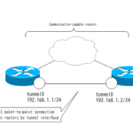
ポイントツーポイントGREトンネルのオーバーレイネットワークをVRFでアンダーレイネットワークと分離します。そのうえで、オーバーレイネットワークとアンダーレイネットワークの関連付けが必要です。そのための設定コマンドがtunnel vrfコマンドです。
関連記事
FVRFの概要について、以下の記事で解説しています。
GREトンネルインタフェースについて、以下の記事で解説しています。
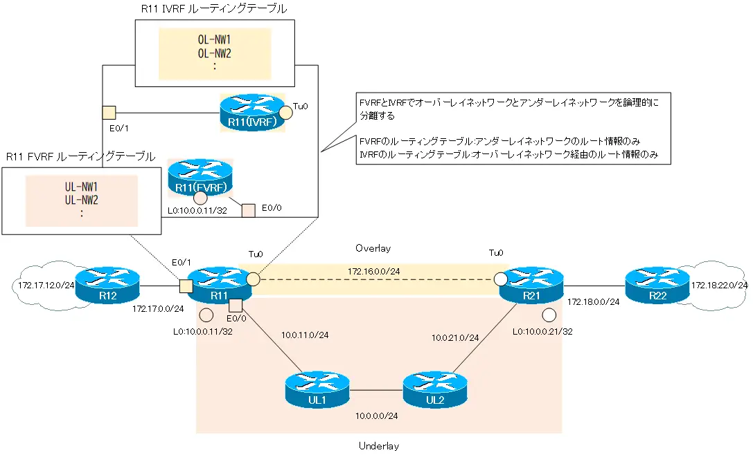
FVRFとIVRF
オーバーレイネットワークとアンダーレイネットワークを1つのグローバルルーティングプロセスで処理すると、さまざまなルート制御が必要です。より安定したオーバーレイネットワークを構築するために、VRFを利用します。
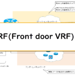
- FVRF(Front door VRF)
- IVRF(Inside VRF)
FVRFは、アンダーレイネットワーク用のVRFとして設定します。そして、IVRFはオーバーレイネットワーク用のVRFとして設定します。
オーバーレイネットワークは、VRFではなくグローバルルーティングプロセス(デフォルトVRF)を利用してもOKです。
IVRFのルーティングテーブルには、オーバーレイネットワーク経由のルート情報のみが登録されます。そして、FVRFのルーティングテーブルには、アンダーレイネットワークのルート情報のみが登録されます。
tunnel vrfコマンド
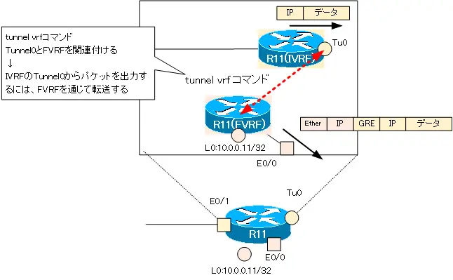
ここで、IVRFのTunnle0インタフェースからパケットを出力するときについて考えます。
Tunnel0(IVRF)から出力するパケットは、実際には、アンダーレイネットワーク(FVRF)を通じて転送されます。そのために、GREヘッダとアンダーレイネットワーク(FVRF)上を転送するための新しいIPヘッダを付加することになります。ところが、IVRFのルーティングテーブルにはFVRFのルート情報がありません。つまり、アンダーレイネットワーク上を転送するための新しいIPヘッダを付加できません。
IVRFのTunnel0からパケットを出力するときに、実際に転送することになる、FVRFとの関連付けが必要です。tunnel vrfコマンドによって、IVRFのTunnelインタフェースからパケットを出力するためのFVRFを関連付けます。
tunnel vrfコマンドのフォーマットは以下の通りです。
tunnel vrfコマンド
(config)#interface tunnel <interface-number>
(config-if)#tunnel vrf <fvrf-name>
<interface-number> : Tunnelインタフェース番号
<fvrf-name> : 関連付けるFVRF名
tunnel vrfコマンドで関連付けたVRFのルーティングテーブルに基づいて、tunnel destinationのIPアドレスへ到達性を見ることになります。なお、tunnel vrfコマンドで関連付けたVRFは、show ip interface tunnelコマンドで確認できます。
show interface tunnel
R11#show ip int tunnel 0
Tunnel0 is up, line protocol is up
  Internet address is 172.16.0.11/24
  Broadcast address is 255.255.255.255
  Address determined by non-volatile memory
  MTU is 1476 bytes
~省略~
  VPN Routing/Forwarding "IVRF"
  Downstream VPN Routing/Forwarding ""
  Tunnel VPN Routing/Forwarding "FVRF"
~省略~
FVRFを利用するGREオーバーレイネットワーク(tunnel vrf)の設定例
ネットワーク構成
次のネットワーク構成を考えます。「[FVRFの仕組み] ポイントツーポイントGREトンネル:FVRFなし」と同じネットワーク構成です。

R11-R12間でポイントツーポイントGREトンネルのオーバーレイネットワークを構築します。そして、オーバーレイネットワークとアンダーレイネットワークをVRFで分離します。VRFとして、以下のような設定を行います。
| ルータ | VRF名 | RD | インタフェース |
|---|---|---|---|
| R11 | FVRF | 65001:100 | Lo0 Eth0/0 |
| IVRF | 65001:200 | Tunnel0 Eth0/1 | |
| R21 | FVRF | 65001:100 | Lo0 Eth0/0 |
| IVRF | 65001:200 | Tunnel0 Eth0/1 |
また、オーバーレイネットワークのIVRFとアンダーレイネットワークのFVRFのアドレス範囲は、重複しないようにしています。IVRFは、172.16.x.xおよび172.17.x.x、172.18.x.xといったクラスBのプライベートアドレスでアドレッシングしています。そして、FVRFは、10.x.x.xのクラスAのプライベートアドレスでアドレッシングしています。
ルーティングプロトコルとして、IVRFはEIGRPを利用し、FVRFではOSPFを利用します。
| アドレス範囲 | ルーティングプロトコル | |
|---|---|---|
| オーバーレイネットワーク(IVRF) | 172.16.0.0/16 172.17.0.0/16 172.18.0.0/16 | EIGRP |
| アンダーレイネットワーク(FVRF) | 10.0.0.0/8 | OSPF |
初期設定
FVRF/IVRFに分離していない状態から設定を行います。各機器の初期設定の抜粋です。
R11 設定抜粋(Click)
hostname R11
!
interface Loopback0
 ip address 10.0.0.11 255.255.255.255
!
interface Tunnel0
 ip address 172.16.0.11 255.255.255.0
 tunnel source Loopback0
 tunnel destination 10.0.0.21
!
interface Ethernet0/0
 ip address 10.0.11.11 255.255.255.0
!
interface Ethernet0/1
 ip address 172.17.0.11 255.255.255.0
!
router eigrp 1
 network 172.16.0.0
 network 172.17.0.0
 eigrp router-id 11.11.11.11
!
router ospf 1
 router-id 11.11.11.11
 network 10.0.0.11 0.0.0.0 area 0
 network 10.0.11.11 0.0.0.0 area 0
R21 設定抜粋(Click)
hostname R21
!
interface Loopback0
 ip address 10.0.0.21 255.255.255.255
!
interface Tunnel0
 ip address 172.16.0.21 255.255.255.0
 tunnel source Loopback0
 tunnel destination 10.0.0.11
!
interface Ethernet0/0
 ip address 10.0.21.21 255.255.255.0
!
interface Ethernet0/1
 ip address 172.18.0.21 255.255.255.0
!
router eigrp 1
 network 172.16.0.0
 network 172.18.0.0
 eigrp router-id 21.21.21.21
!
router ospf 1
 router-id 21.21.21.21
 network 10.0.0.21 0.0.0.0 area 0
 network 10.0.21.21 0.0.0.0 area 0
R12 設定抜粋(Click)
hostname R12
!
interface Loopback0
 ip address 172.17.12.12 255.255.255.0
 ip ospf network point-to-point
!
interface Ethernet0/0
 ip address 172.17.0.12 255.255.255.0
!
router eigrp 1
 network 172.17.0.0
 eigrp router-id 12.12.12.12
R22 設定抜粋(Click)
hostname R22
!
interface Loopback0
 ip address 172.18.22.22 255.255.255.0
 ip ospf network point-to-point
!
interface Ethernet0/0
 ip address 172.18.0.22 255.255.255.0
!
router eigrp 1
 network 172.18.0.0
 eigrp router-id 22.22.22.22
UL1 設定抜粋(Click)
hostname UL1
!
interface Ethernet0/0
 ip address 10.0.11.1 255.255.255.0
!
interface Ethernet0/1
 ip address 10.0.0.1 255.255.255.0
!
router ospf 1
 router-id 1.1.1.1
 network 10.0.0.0 0.255.255.255 area 0
UL2 設定抜粋(Click)
hostname UL2
!
interface Ethernet0/0
 ip address 10.0.21.2 255.255.255.0
!
interface Ethernet0/1
 ip address 10.0.0.2 255.255.255.0
!
router ospf 1
 router-id 2.2.2.2
 network 10.0.0.0 0.255.255.255 area 0
設定と確認
Step1: VRFの作成とインタフェースの割り当て
オーバーレイネットワークとアンダーレイネットワークの境界のR11/R21で、VRFによってオーバーレイネットワークとアンダーレイネットワークを分離します。VRFを作成して、インタフェースの割り当てを行います。
R11 VRFの作成とインタフェースの割り当て
ip vrf FVRF
 rd 65001:100
!
ip vrf IVRF
 rd 65001:200
!
interface Loopback0
 ip vrf forwarding FVRF
 ip address 10.0.0.11 255.255.255.255
!
interface Tunnel0
 ip vrf forwarding IVRF
 ip address 172.16.0.11 255.255.255.0
!
interface Ethernet0/0
 ip vrf forwarding FVRF
 ip address 10.0.11.11 255.255.255.0
!
interface Ethernet0/1
 ip vrf forwarding IVRF
 ip address 172.17.0.11 255.255.255.0
R21 VRFの作成とインタフェースの割り当て
ip vrf FVRF
 rd 65100:100
!
ip vrf IVRF
 rd 65100:200
!
interface Loopback0
 ip vrf forwarding FVRF
 ip address 10.0.0.21 255.255.255.255
!
interface Tunnel0
 ip vrf forwarding IVRF
 ip address 172.16.0.21 255.255.255.0
!
interface Ethernet0/0
 ip vrf forwarding FVRF
 ip address 10.0.21.21 255.255.255.0
!
interface Ethernet0/1
 ip vrf forwarding IVRF
 ip address 172.18.0.21 255.255.255.0
Step2: VRFの作成とインタフェースの割り当ての確認
show ip vrfコマンドで作成したVRFとインタフェースの割り当てを確認します。R11では、次のような表示です。
R11 show ip vrf
R11#show ip vrf
  Name                             Default RD            Interfaces
  FVRF                             65001:100             Lo0
                                                         Et0/0
  IVRF                             65001:200             Tu0
                                                         Et0/1
ただし、Tunnel0インタフェースはup/downの状態です。
R11 show interface tunnel0/show ip interface tunnel0
R11#show interface tunnel 0
Tunnel0 is up, line protocol is down
  Hardware is Tunnel
  Internet address is 172.16.0.11/24
  MTU 17916 bytes, BW 100 Kbit/sec, DLY 50000 usec,
     reliability 255/255, txload 1/255, rxload 1/255
  Encapsulation TUNNEL, loopback not set
  Keepalive not set
  Tunnel linestate evaluation down - no output interface
  Tunnel source 10.0.0.11 (Loopback0), destination 10.0.0.21
   Tunnel Subblocks:
      src-track:
         Tunnel0 source tracking subblock associated with Loopback0
          Set of tunnels with source Loopback0, 1 member (includes iterators), on interface
  Tunnel protocol/transport GRE/IP
    Key disabled, sequencing disabled
    Checksumming of packets disabled
~省略~
R11#show ip interface tunnel 0
Tunnel0 is up, line protocol is down
  Internet address is 172.16.0.11/24
  Broadcast address is 255.255.255.255
  Address determined by non-volatile memory
  MTU is 1476 bytes
  Helper address is not set
  Directed broadcast forwarding is disabled
  Multicast reserved groups joined: 224.0.0.10
~省略~
  VPN Routing/Forwarding "IVRF"
  Downstream VPN Routing/Forwarding ""
~省略~
これは、tunnel destinationの10.0.0.21への接続性がないためです。デフォルトはグローバルルーティングテーブルでtunnel destinationへの接続性を確認します。
Step3: tunnel vrfコマンドの設定
IVRFのtunnel0からパケットを出力するときに、FVRFを通じて転送できるようにtunnel vrfコマンドを設定します。
R11/R21 tunnel vrf
interface tunnel0
 tunnel vrf FVRF
Step4: tunnel vrfコマンドの確認
tunnel vrfコマンドで、tunnel0とアンダーレイネットワークのFVRFを関連付けました。でも、まだtunnel0はup/downです。
R11 show ip interface tunnel0
R11#show ip int tunnel 0
Tunnel0 is up, line protocol is down
  Internet address is 172.16.0.11/24
  Broadcast address is 255.255.255.255
  Address determined by non-volatile memory
  MTU is 1476 bytes
  Helper address is not set
  Directed broadcast forwarding is disabled
  Multicast reserved groups joined: 224.0.0.10
~省略~
  VPN Routing/Forwarding "IVRF"
  Downstream VPN Routing/Forwarding ""
  Tunnel VPN Routing/Forwarding "FVRF"
~省略~
Tunnel0がまだup/down状態なのは、FVRFのルーティングテーブルにはtunnel destinationの10.0.0.21へのルートがないからです。
R11 show ip route vrf FVRF
R11#show ip route vrf FVRF

Routing Table: FVRF
~省略~

Gateway of last resort is not set

      10.0.0.0/8 is variably subnetted, 3 subnets, 2 masks
C        10.0.0.11/32 is directly connected, Loopback0
C        10.0.11.0/24 is directly connected, Ethernet0/0
L        10.0.11.11/32 is directly connected, Ethernet0/0
FVRFのルーティングテーブルを作り上げて、tunnel destinationへの到達性を確保します。
Step5: VRFごとのルーティングの設定
R11/R21をVRFに分割したら、VRFごとのルーティングの設定もしなければいけません。FVRFのルーティングの設定は以下です。FVRFはOSPFを利用します。
R11 FVRFのルーティング(OSPF)の設定
no router ospf 1
router ospf 1 vrf FVRF
 router-id 11.11.11.11
 network 10.0.0.11 0.0.0.0 area 0
 network 10.0.11.11 0.0.0.0 area 0
R21 FVRFのルーティング(OSPF)の設定
no router ospf 1
router ospf 1 vrf FVRF
 router-id 21.21.21.21
 network 10.0.0.21 0.0.0.0 area 0
 network 10.0.21.21 0.0.0.0 area 0
そして、IVRFはEIGRPでルーティングを行います。
R11 IVRFのルーティング(EIGRP)の設定
no router eigrp 1
router eigrp 1
 !
 address-family ipv4 vrf IVRF autonomous-system 1
  network 172.16.0.0
  network 172.17.0.0
 exit-address-family
 eigrp router-id 11.11.11.11
R21 IVRFのルーティング(EIGRP)の設定
no router eigrp 1
router eigrp 1
 !
 address-family ipv4 vrf IVRF autonomous-system 1
  network 172.16.0.0
  network 172.18.0.0
 exit-address-family
 eigrp router-id 21.21.21.21
以下の図で、R11のVRFごとのルーティングプロトコルをまとめています。
Step6: VRFごとのルーティングの確認
FVRF/IVRFのルーティングプロトコルの設定が正しくできれば、それぞれのVRFのルーティングテーブルができ上がります。R11のルーティングテーブルは次の通りです。
R11VRFごとのルーティングテーブル
R11#show ip route vrf FVRF

Routing Table: FVRF
~省略~

Gateway of last resort is not set

      10.0.0.0/8 is variably subnetted, 6 subnets, 2 masks
O        10.0.0.0/24 [110/20] via 10.0.11.1, 00:08:40, Ethernet0/0
C        10.0.0.11/32 is directly connected, Loopback0
O        10.0.0.21/32 [110/31] via 10.0.11.1, 00:08:40, Ethernet0/0
C        10.0.11.0/24 is directly connected, Ethernet0/0
L        10.0.11.11/32 is directly connected, Ethernet0/0
O        10.0.21.0/24 [110/30] via 10.0.11.1, 00:08:40, Ethernet0/0
R11#show ip route vrf IVRF

Routing Table: IVRF
~省略~

Gateway of last resort is not set

      172.16.0.0/16 is variably subnetted, 2 subnets, 2 masks
C        172.16.0.0/24 is directly connected, Tunnel0
L        172.16.0.11/32 is directly connected, Tunnel0
      172.17.0.0/16 is variably subnetted, 3 subnets, 2 masks
C        172.17.0.0/24 is directly connected, Ethernet0/1
L        172.17.0.11/32 is directly connected, Ethernet0/1
D        172.17.12.0/24 [90/409600] via 172.17.0.12, 00:59:47, Ethernet0/1
      172.18.0.0/24 is subnetted, 2 subnets
D        172.18.0.0 [90/26905600] via 172.16.0.21, 00:08:43, Tunnel0
D        172.18.22.0 [90/27033600] via 172.16.0.21, 00:08:43, Tunnel0
このように、R11ではVRFによって、アンダーレイネットワークとオーバーレイネットワークが分離されています。
これで、FVRF/IVRFでアンダーレイネットワークとオーバーレイネットワークを分離するための設定はすべて完了です。
Step7: 通信確認
オーバーレイネットワークの通信が正常にできることを確認します。R12からR22へPingを実行します。
R12からR22へPing
R12#ping 172.18.22.22 source 172.17.12.12
Type escape sequence to abort.
Sending 5, 100-byte ICMP Echos to 172.18.22.22, timeout is 2 seconds:
Packet sent with a source address of 172.17.12.12
!!!!!
Success rate is 100 percent (5/5), round-trip min/avg/max = 1/1/2 ms
オーバーレイネットワークの通信が正常にできていることがわかります。
R12からR22宛てのPingをR11 E0/1でキャプチャすると、次のような内容です。
設定コマンドのまとめ
初期設定の状態からR11/R21に設定した設定コマンドのまとめです。
R11 設定コマンドのまとめ
ip vrf FVRF
 rd 65001:100
!
ip vrf IVRF
 rd 65001:200
!
interface Loopback0
 ip vrf forwarding FVRF
 ip address 10.0.0.11 255.255.255.255
!
interface Tunnel0
 ip vrf forwarding IVRF
 ip address 172.16.0.11 255.255.255.0
 tunnel vrf FVRF
!
interface Ethernet0/0
 ip vrf forwarding FVRF
 ip address 10.0.11.11 255.255.255.0
!
interface Ethernet0/1
 ip vrf forwarding IVRF
 ip address 172.17.0.11 255.255.255.0
!
router eigrp 1
 !
 address-family ipv4 vrf IVRF autonomous-system 1
  network 172.16.0.0
  network 172.17.0.0
 exit-address-family
 eigrp router-id 11.11.11.11
!
router ospf 1 vrf FVRF
 router-id 11.11.11.11
 network 10.0.0.11 0.0.0.0 area 0
 network 10.0.11.11 0.0.0.0 area 0
R21 設定コマンドのまとめ
ip vrf FVRF
 rd 65100:100
!
ip vrf IVRF
 rd 65100:200
!
interface Loopback0
 ip vrf forwarding FVRF
 ip address 10.0.0.21 255.255.255.255
!
interface Tunnel0
 ip vrf forwarding IVRF
 ip address 172.16.0.21 255.255.255.0
 tunnel vrf FVRF
!
interface Ethernet0/0
 ip vrf forwarding FVRF
 ip address 10.0.21.21 255.255.255.0
!
interface Ethernet0/1
 ip vrf forwarding IVRF
 ip address 172.18.0.21 255.255.255.0
!
router eigrp 1
 !
 address-family ipv4 vrf IVRF autonomous-system 1
  network 172.16.0.0
  network 172.18.0.0
 exit-address-family
 eigrp router-id 21.21.21.21
!
router ospf 1 vrf FVRF
 router-id 21.21.21.21
 network 10.0.0.21 0.0.0.0 area 0
 network 10.0.21.21 0.0.0.0 area 0
まとめ
ポイント
- アンダーレイネットワーク用のFVRF(Front door VRF)とオーバーレイネットワーク用のIVRF(Inside VRF)に分割して、より安定したオーバーレイネットワークを構築します。
- IVRFのTunnelインタフェースとFVRFを関連付けるためにtunnel vrfコマンドを利用します。

IPルーティング応用
- DNSラウンドロビン方式の負荷分散
- 負荷分散装置(ロードバランサ)の仕組み
- ルーティングプロセス ~実行中のルーティングプロトコル用のプログラム~
- 複数のルーティングプロトコルの利用
- 再配送(再配布) ~ルーティングドメイン境界で必須の設定~
- Cisco再配送(再配布)の設定 ~redistributeコマンド~
- Cisco 再配送の設定例 ~OSPFとRIPの双方向再配送~
- 再配送 設定ミスの切り分けと修正 Part1
- 再配送 設定ミスの切り分けと修正 Part2
- 再配送 設定ミスの切り分けと修正 Part3
- 再配送 設定ミスの切り分けと修正 Part4
- 再配送 設定ミスの切り分けと修正 Part5
- 再配送 設定ミスの切り分けと修正 Part6
- オフセットリスト(offset-list) ~ルート情報のメトリックを加算~
- オフセットリストの設定例 RIP
- オフセットリストの設定例 EIGRP
- ルートフィルタの概要
- ルートフィルタのポイント
- ディストリビュートリストによるルートフィルタの設定
- Ciscoディストリビュートリストによるルートフィルタの設定例
- プレフィクスリスト(prefix-list)によるルートフィルタの設定
- Ciscoプレフィクスリストによるルートフィルタの設定例
- Ciscoルートマップ(route-map)の概要 ~何をどう処理するか~
- Ciscoルートマップの設定
- Ciscoルートマップ(route-map)設定のポイント
- Ciscoルートマップによる再配送時のルート制御の設定例
- ポリシーベースルーティングの設定例
- GREトンネルインタフェース ~仮想的なポイントツーポイント接続~
- GREトンネルインタフェースの設定例
- GREトンネルの注意点 ~フラッピングしないように~
- オーバーレイネットワークとアンダーレイネットワーク
- ルート制御 ケーススタディ Part1
- ルート制御 ケーススタディ Part2
- ルート制御 ケーススタディ Part3
- VRF/VRF-Liteの概要 ~仮想的にルータを分割する~
- VRFの設定と確認コマンド [Cisco]
- VRF-Liteによるレイヤ3VPNの設定例 [Cisco]
- VRFルートリーク(スタティックルート)
- VRFルートリーク(スタティックルート)の設定例
- VRFルートリーク(MP-BGP)
- VRFルートリーク(MP-BGP)の設定例
- [FVRFの仕組み] FVRF(Front door VRF)とは
- [FVRFの仕組み] ポイントツーポイントGREトンネル:FVRFなし
- [FVRFの仕組み] ポイントツーポイントGREトンネル : FVRFあり(tunnel vrfコマンド)
- [FVRFの仕組み] IPSec VTI : FRVRFあり
- [FVRFの仕組み] IPSec VTI : FVRFあり 設定例
- [FVRFの仕組み] DMVPN : FVRFあり
- [FVRFの仕組み] DMVPN : FVRFあり 設定例 Part1
- [FVRFの仕組み] DMVPN : FVRFあり 設定例 Part2
- tunnel vrfコマンド
- tunnel vrfコマンドの設定例
- [演習] ルーティングループの防止
- [演習] 企業ネットワーク構築演習 Part1:拠点1の構築
- [演習] 企業ネットワーク構築演習 Part2:拠点2/拠点3の構築
- [演習] 企業ネットワーク構築演習 Part3:広域イーサネットの接続
- [演習] 企業ネットワーク構築演習 Part4:インターネット(AS1/AS2)の構築
- [演習] 企業ネットワーク構築演習 Part5:インターネットへの接続
- [演習] 企業ネットワーク構築演習 Part6:インターネットVPNの構築