
Table of Contents
概要
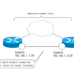
インターネット経由でGREトンネルを設定します。これにより、2つの拠点間を仮想的にポイントツーポイント接続として、簡易的なインターネットVPNを構築します。
関連記事
ネットワーク構成
下記のネットワーク構成でR11とR21間でGREトンネルを設定して、R11とR21をポイントツーポイントで接続します。そして、拠点1と拠点2間の通信ができるようにGREトンネル上でRIPを利用してルーティングテーブルを作成します。
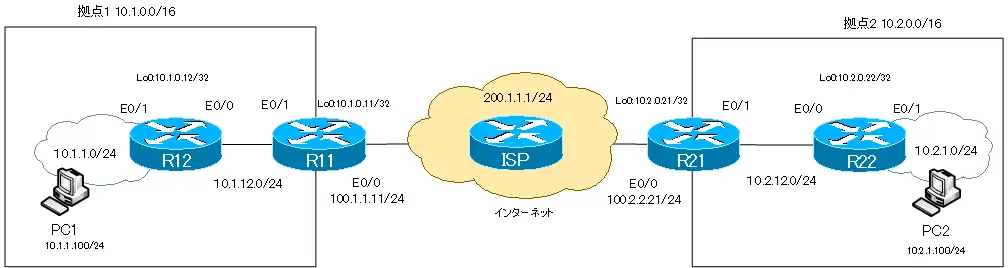
GREトンネルインタフェースを設定するためには、R11とR21間が通信可能な状態であることが前提です。そのために、R11/R21でデフォルトルートをスタティックルートとして設定しています。
GREトンネルインタフェースの設定と確認
GREトンネルインタフェースの設定
R11とR21でトンネルインタフェースを作成します。インタフェース番号は何でもOKで、ここでは0とします。tunnel destinationとtunnel sourceコマンドで転送用のIPヘッダの宛先IPアドレス/送信元IPアドレスを指定します。R11とR12でお互いの認識があっていなければいけません。また、Tunnel0上でIPパケットを送受信するためには、IPアドレスが必要です。明示的にIPアドレスを設定する代わりにLoopback0のIPアドレスを使い回すように、ip unnumberedの設定をしています。
R11
interface Tunnel0
 ip unnumbered Loopback0
 tunnel source Ethernet0/0
 tunnel destination 100.2.2.21
R21
interface Tunnel0
 ip unnumbered Loopback0
 tunnel source Ethernet0/0
 tunnel destination 100.1.1.11
GREトンネルインタフェースの確認
show interface tunnel0コマンドでR11-R21間のトンネルインタフェースを確認します。R11でのshow interface tunnel0の出力は次のようになります。
R11
R11#show interfaces tunnel 0
Tunnel0 is up, line protocol is up
  Hardware is Tunnel
  Interface is unnumbered. Using address of Loopback0 (10.1.0.11)
  MTU 1514 bytes, BW 9 Kbit/sec, DLY 500000 usec,
     reliability 255/255, txload 1/255, rxload 1/255
  Encapsulation TUNNEL, loopback not set
  Keepalive not set
  Tunnel source 100.1.1.11 (Ethernet0/0), destination 100.2.2.21
  Tunnel protocol/transport GRE/IP
    Key disabled, sequencing disabled
    Checksumming of packets disabled
  Tunnel TTL 255
  Fast tunneling enabled
  Tunnel transmit bandwidth 8000 (kbps)
  Tunnel receive bandwidth 8000 (kbps)
~省略~
RIPの有効化
GREトンネル経由で拠点1と拠点2間の通信ができるようにRIPでルーティングを行います。
R11/R12/R21/R22
router rip
 network 10.0.0.0
 version 2
 no auto-summary
GREトンネルにはip unnumberedでLoopback0と同じIPアドレスを設定しています。そのため、Loopback0でRIPが有効になれば、同時にtunnel0でもRIPが有効になります。
ルーティングの確認
GREトンネルでRIPを有効にしていて、GREトンネル経由でお互いの拠点のルート情報を学習できています。R11でルーティングの状態を確認すると次のようになります。
R11
R11#show ip protocols
Routing Protocol is "rip"
  Outgoing update filter list for all interfaces is not set
  Incoming update filter list for all interfaces is not set
  Sending updates every 30 seconds, next due in 20 seconds
  Invalid after 180 seconds, hold down 180, flushed after 240
  Redistributing: rip
  Default version control: send version 2, receive version 2
    Interface             Send  Recv  Triggered RIP  Key-chain
    Ethernet0/1           2     2
    Loopback0             2     2
    Tunnel0               2     2
  Automatic network summarization is not in effect
  Maximum path: 4
  Routing for Networks:
    10.0.0.0
  Routing Information Sources:
    Gateway         Distance      Last Update
    10.1.12.12           120      00:00:01
    10.2.0.21            120      00:00:27
  Distance: (default is 120)

R11#show ip route
~省略~

Gateway of last resort is 100.1.1.100 to network 0.0.0.0

     100.0.0.0/24 is subnetted, 1 subnets
C       100.1.1.0 is directly connected, Ethernet0/0
     10.0.0.0/8 is variably subnetted, 8 subnets, 2 masks
R       10.2.12.0/24 [120/1] via 10.2.0.21, 00:00:03, Tunnel0
C       10.1.12.0/24 is directly connected, Ethernet0/1
R       10.1.0.12/32 [120/1] via 10.1.12.12, 00:00:05, Ethernet0/1
R       10.2.1.0/24 [120/2] via 10.2.0.21, 00:00:03, Tunnel0
R       10.1.1.0/24 [120/1] via 10.1.12.12, 00:00:05, Ethernet0/1
C       10.1.0.0/24 is directly connected, Loopback0
R       10.2.0.21/32 [120/1] via 10.2.0.21, 00:00:04, Tunnel0
R       10.2.0.22/32 [120/2] via 10.2.0.21, 00:00:04, Tunnel0
S*   0.0.0.0/0 [1/0] via 100.1.1.100
拠点間の通信確認
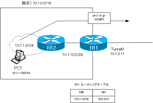
拠点間の通信としてPC1-PC2間の通信を確認します。PC1からPC2へPingを実行します。
PC1
PC1> ping 10.2.1.100
84 bytes from 10.2.1.100 icmp_seq=1 ttl=60 time=103.327 ms
84 bytes from 10.2.1.100 icmp_seq=2 ttl=60 time=89.114 ms
84 bytes from 10.2.1.100 icmp_seq=3 ttl=60 time=78.018 ms
84 bytes from 10.2.1.100 icmp_seq=4 ttl=60 time=98.787 ms
84 bytes from 10.2.1.100 icmp_seq=5 ttl=60 time=102.156 ms
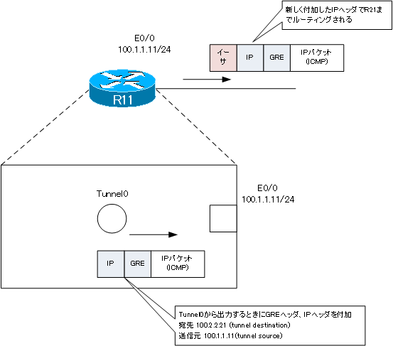
PC1からPC2へのPingを実行したときのICMPパケットは、R11でtunnel0インタフェースから出力されます。
tunnel0インタフェースから出力するとGREヘッダと新しいIPヘッダが付加され、E0/0から出力されます。新しいIPヘッダによってR21までルーティングされます。

IPルーティング応用
- DNSラウンドロビン方式の負荷分散
- 負荷分散装置(ロードバランサ)の仕組み
- ルーティングプロセス ~実行中のルーティングプロトコル用のプログラム~
- 複数のルーティングプロトコルの利用
- 再配送(再配布) ~ルーティングドメイン境界で必須の設定~
- Cisco再配送(再配布)の設定 ~redistributeコマンド~
- Cisco 再配送の設定例 ~OSPFとRIPの双方向再配送~
- 再配送 設定ミスの切り分けと修正 Part1
- 再配送 設定ミスの切り分けと修正 Part2
- 再配送 設定ミスの切り分けと修正 Part3
- 再配送 設定ミスの切り分けと修正 Part4
- 再配送 設定ミスの切り分けと修正 Part5
- 再配送 設定ミスの切り分けと修正 Part6
- オフセットリスト(offset-list) ~ルート情報のメトリックを加算~
- オフセットリストの設定例 RIP
- オフセットリストの設定例 EIGRP
- ルートフィルタの概要
- ルートフィルタのポイント
- ディストリビュートリストによるルートフィルタの設定
- Ciscoディストリビュートリストによるルートフィルタの設定例
- プレフィクスリスト(prefix-list)によるルートフィルタの設定
- Ciscoプレフィクスリストによるルートフィルタの設定例
- Ciscoルートマップ(route-map)の概要 ~何をどう処理するか~
- Ciscoルートマップの設定
- Ciscoルートマップ(route-map)設定のポイント
- Ciscoルートマップによる再配送時のルート制御の設定例
- ポリシーベースルーティングの設定例
- GREトンネルインタフェース ~仮想的なポイントツーポイント接続~
- GREトンネルインタフェースの設定例
- GREトンネルの注意点 ~フラッピングしないように~
- オーバーレイネットワークとアンダーレイネットワーク
- ルート制御 ケーススタディ Part1
- ルート制御 ケーススタディ Part2
- ルート制御 ケーススタディ Part3
- VRF/VRF-Liteの概要 ~仮想的にルータを分割する~
- VRFの設定と確認コマンド [Cisco]
- VRF-Liteによるレイヤ3VPNの設定例 [Cisco]
- VRFルートリーク(スタティックルート)
- VRFルートリーク(スタティックルート)の設定例
- VRFルートリーク(MP-BGP)
- VRFルートリーク(MP-BGP)の設定例
- [FVRFの仕組み] FVRF(Front door VRF)とは
- [FVRFの仕組み] ポイントツーポイントGREトンネル:FVRFなし
- [FVRFの仕組み] ポイントツーポイントGREトンネル : FVRFあり(tunnel vrfコマンド)
- [FVRFの仕組み] IPSec VTI : FRVRFあり
- [FVRFの仕組み] IPSec VTI : FVRFあり 設定例
- [FVRFの仕組み] DMVPN : FVRFあり
- [FVRFの仕組み] DMVPN : FVRFあり 設定例 Part1
- [FVRFの仕組み] DMVPN : FVRFあり 設定例 Part2
- tunnel vrfコマンド
- tunnel vrfコマンドの設定例
- [演習] ルーティングループの防止
- [演習] 企業ネットワーク構築演習 Part1:拠点1の構築
- [演習] 企業ネットワーク構築演習 Part2:拠点2/拠点3の構築
- [演習] 企業ネットワーク構築演習 Part3:広域イーサネットの接続
- [演習] 企業ネットワーク構築演習 Part4:インターネット(AS1/AS2)の構築
- [演習] 企業ネットワーク構築演習 Part5:インターネットへの接続
- [演習] 企業ネットワーク構築演習 Part6:インターネットVPNの構築