
Table of Contents
概要
スタティックルートでVRFルートリークの設定を行って、VRF間で通信できるようにするための設定例です。
関連記事
CiscoでのVRFの設定と確認コマンドは以下の記事で解説しています。
VRFルートリークについて以下の記事で解説しています。
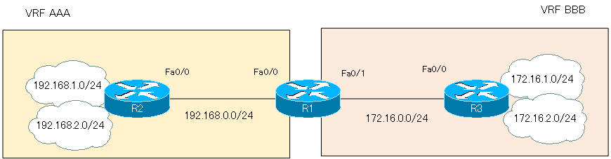
ネットワーク構成
設定条件
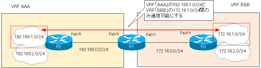
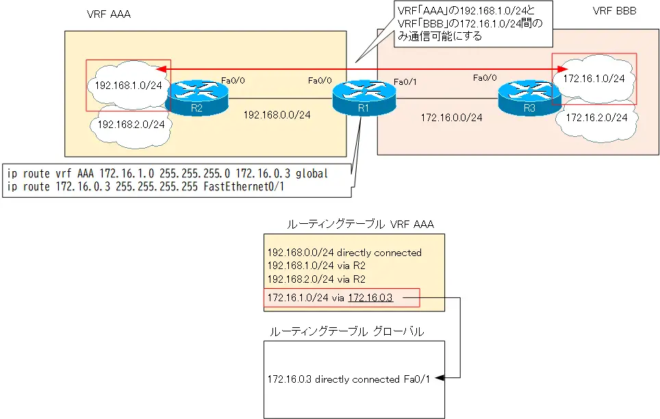
- VRF「AAA」の192.168.1.0/24とVRF「BBB」の172.16.1.0/24間でのみ通信できるように、R1でスタティックルートを設定します。
初期設定
R1でVRF「AAA」とVRF「BBB」を作成して、それぞれインタフェースの割当を行っています。また、VRF「AAA」内のルーティングができるようにR1/R2でスタティックルートの設定を行っています。同様にVRF「BBB」内でルーティングできるようにR1/R3でスタティックルートの設定も行っています。
R1 初期設定抜粋(Click)
hostname R1
!
ip vrf AAA
 rd 1:100
!
ip vrf BBB
 rd 1:200
!
interface FastEthernet0/0
 ip vrf forwarding AAA
 ip address 192.168.0.1 255.255.255.0
!
interface FastEthernet0/1
 ip vrf forwarding BBB
 ip address 172.16.0.1 255.255.255.0
!
ip route vrf AAA 192.168.0.0 255.255.0.0 192.168.0.2
ip route vrf BBB 172.16.0.0 255.255.0.0 172.16.0.3
R2 初期設定抜粋(Click)
hostname R2
!
interface Loopback1
 ip address 192.168.1.2 255.255.255.0
!
interface Loopback2
 ip address 192.168.2.2 255.255.255.0
!
interface FastEthernet0/0
 ip address 192.168.0.2 255.255.255.0
!
ip route 0.0.0.0 0.0.0.0 192.168.0.1
R3 初期設定抜粋(Click)
hostname R3
!
interface Loopback1
 ip address 172.16.1.3 255.255.255.0
!
interface Loopback2
 ip address 172.16.2.3 255.255.255.0
!
interface FastEthernet0/0
 ip address 172.16.0.3 255.255.255.0
!
ip route 0.0.0.0 0.0.0.0 172.16.0.1
設定と確認
Step1:VRF間の通信の確認
VRFルートリークの設定を行っていない状態でVRF間の通信を確認します。R2からR3へPingを実行します。
R2 VRF間の通信の確認
R2#ping 172.16.1.3 source loopback 1

Type escape sequence to abort.
Sending 5, 100-byte ICMP Echos to 172.16.1.3, timeout is 2 seconds:
Packet sent with a source address of 192.168.1.2
.UUUU
Success rate is 0 percent (0/5)
R2#ping 172.16.1.3 source loopback 2

Type escape sequence to abort.
Sending 5, 100-byte ICMP Echos to 172.16.1.3, timeout is 2 seconds:
Packet sent with a source address of 192.168.2.2
UUUUU
Success rate is 0 percent (0/5)
R2#ping 172.16.2.3 source loopback 1

Type escape sequence to abort.
Sending 5, 100-byte ICMP Echos to 172.16.2.3, timeout is 2 seconds:
Packet sent with a source address of 192.168.1.2
UUUUU
Success rate is 0 percent (0/5)
R2#ping 172.16.2.3 source loopback 2

Type escape sequence to abort.
Sending 5, 100-byte ICMP Echos to 172.16.2.3, timeout is 2 seconds:
Packet sent with a source address of 192.168.2.2
UUUUU
Success rate is 0 percent (0/5)
VRF「AAA」とVRF「BBB」間の通信はできないことがわかります。
Step2:VRF「AAA」に172.16.1.0/24のスタティックルートを登録
R1でVRF「AAA」のルーティングテーブルに、通信させたいVRF「BBB」の172.168.1.0/24のスタティックルートを登録します。ネクストホップを解決するためにグローバルルーティングテーブルを参照するようにします。
R1 VRF「AAA」に172.16.1.0/24を登録
ip route vrf AAA 172.16.1.0 255.255.255.0 172.16.0.3 global
ip route 172.16.0.3 255.255.255.255 FastEthernet0/1
Step3:VRF「AAA」のルーティングテーブルを確認
VRF「AAA」のルーティングテーブルにVRF「BBB」の172.16.1.0/24が登録されていることを確認します。また、グローバルルーティングテーブルも確認します。
R1 ルーティングテーブルの確認
R1#show ip route vrf AAA

Routing Table: AAA
~省略~

Gateway of last resort is not set

     172.16.0.0/24 is subnetted, 1 subnets
S       172.16.1.0 [1/0] via 172.16.0.3
C    192.168.0.0/24 is directly connected, FastEthernet0/0
S    192.168.0.0/16 [1/0] via 192.168.0.2
R1#show ip route
~省略~

Gateway of last resort is not set

     172.16.0.0/32 is subnetted, 1 subnets
S       172.16.0.3 is directly connected, FastEthernet0/1
Step4:VRF「BBB」に192.168.1.0/24のスタティックルートを登録
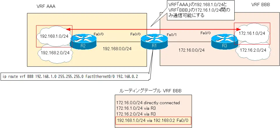
R1でVRF「BBB」のルーティングテーブルに通信させたいVRF「AAA」の192.168.1.0/24のスタティックルートを登録します。ネクストホップに加えて出力インタフェースも明示的に指定します。
R1 VRF「BBB」に192.168.1.0/24を登録
ip route vrf BBB 192.168.1.0 255.255.255.0 FastEthernet0/0 192.168.0.2
Step5:VRF「BBB」のルーティングテーブルを確認
VRF「BBB」のルーティングテーブルにVRF「AAA」の192.168.1.0/24のルートが登録されていることを確認します。
R1 ルーティングテーブルの確認
R1#show ip route vrf BBB

Routing Table: BBB
~省略~

Gateway of last resort is not set

     172.16.0.0/16 is variably subnetted, 2 subnets, 2 masks
C       172.16.0.0/24 is directly connected, FastEthernet0/1
S       172.16.0.0/16 [1/0] via 172.16.0.3
S    192.168.1.0/24 [1/0] via 192.168.0.2, FastEthernet0/0
これで、VRF「AAA」の192.168.1.0/24とVRF「BBB」の172.16.1.0/24間の通信ができるようにするルートリークの設定は完了です。
Step6:VRF間の通信の確認
条件通りにVRF「AAA」の192.168.1.0/24とVRF「BBB」の172.16.1.0/24間の通信ができることを確認します。R2からR3へPingを実行します。
R2 VRF間の通信の確認
R2#ping 172.16.1.3 source loopback 1

Type escape sequence to abort.
Sending 5, 100-byte ICMP Echos to 172.16.1.3, timeout is 2 seconds:
Packet sent with a source address of 192.168.1.2
!!!!!
Success rate is 100 percent (5/5), round-trip min/avg/max = 24/29/36 ms
R2#ping 172.16.1.3 source loopback 2

Type escape sequence to abort.
Sending 5, 100-byte ICMP Echos to 172.16.1.3, timeout is 2 seconds:
Packet sent with a source address of 192.168.2.2
.....
Success rate is 0 percent (0/5)
R2#ping 172.16.2.3 source loopback 1

Type escape sequence to abort.
Sending 5, 100-byte ICMP Echos to 172.16.2.3, timeout is 2 seconds:
Packet sent with a source address of 192.168.1.2
UUUUU
Success rate is 0 percent (0/5)
R2#ping 172.16.2.3 source loopback 2

Type escape sequence to abort.
Sending 5, 100-byte ICMP Echos to 172.16.2.3, timeout is 2 seconds:
Packet sent with a source address of 192.168.2.2
UUUUU
Success rate is 0 percent (0/5)
R1の設定コマンドのまとめ
ここまでの手順でR1に設定したVRFルートリークの設定コマンドは以下です。
R1 VRFルートリーク設定コマンドのまとめ
ip route 172.16.0.3 255.255.255.255 FastEthernet0/1
ip route vrf AAA 172.16.1.0 255.255.255.0 172.16.0.3 global
ip route vrf BBB 192.168.1.0 255.255.255.0 FastEthernet0/0 192.168.0.2

IPルーティング応用
- DNSラウンドロビン方式の負荷分散
- 負荷分散装置(ロードバランサ)の仕組み
- ルーティングプロセス ~実行中のルーティングプロトコル用のプログラム~
- 複数のルーティングプロトコルの利用
- 再配送(再配布) ~ルーティングドメイン境界で必須の設定~
- Cisco再配送(再配布)の設定 ~redistributeコマンド~
- Cisco 再配送の設定例 ~OSPFとRIPの双方向再配送~
- 再配送 設定ミスの切り分けと修正 Part1
- 再配送 設定ミスの切り分けと修正 Part2
- 再配送 設定ミスの切り分けと修正 Part3
- 再配送 設定ミスの切り分けと修正 Part4
- 再配送 設定ミスの切り分けと修正 Part5
- 再配送 設定ミスの切り分けと修正 Part6
- オフセットリスト(offset-list) ~ルート情報のメトリックを加算~
- オフセットリストの設定例 RIP
- オフセットリストの設定例 EIGRP
- ルートフィルタの概要
- ルートフィルタのポイント
- ディストリビュートリストによるルートフィルタの設定
- Ciscoディストリビュートリストによるルートフィルタの設定例
- プレフィクスリスト(prefix-list)によるルートフィルタの設定
- Ciscoプレフィクスリストによるルートフィルタの設定例
- Ciscoルートマップ(route-map)の概要 ~何をどう処理するか~
- Ciscoルートマップの設定
- Ciscoルートマップ(route-map)設定のポイント
- Ciscoルートマップによる再配送時のルート制御の設定例
- ポリシーベースルーティングの設定例
- GREトンネルインタフェース ~仮想的なポイントツーポイント接続~
- GREトンネルインタフェースの設定例
- GREトンネルの注意点 ~フラッピングしないように~
- オーバーレイネットワークとアンダーレイネットワーク
- ルート制御 ケーススタディ Part1
- ルート制御 ケーススタディ Part2
- ルート制御 ケーススタディ Part3
- VRF/VRF-Liteの概要 ~仮想的にルータを分割する~
- VRFの設定と確認コマンド [Cisco]
- VRF-Liteによるレイヤ3VPNの設定例 [Cisco]
- VRFルートリーク(スタティックルート)
- VRFルートリーク(スタティックルート)の設定例
- VRFルートリーク(MP-BGP)
- VRFルートリーク(MP-BGP)の設定例
- [FVRFの仕組み] FVRF(Front door VRF)とは
- [FVRFの仕組み] ポイントツーポイントGREトンネル:FVRFなし
- [FVRFの仕組み] ポイントツーポイントGREトンネル : FVRFあり(tunnel vrfコマンド)
- [FVRFの仕組み] IPSec VTI : FRVRFあり
- [FVRFの仕組み] IPSec VTI : FVRFあり 設定例
- [FVRFの仕組み] DMVPN : FVRFあり
- [FVRFの仕組み] DMVPN : FVRFあり 設定例 Part1
- [FVRFの仕組み] DMVPN : FVRFあり 設定例 Part2
- tunnel vrfコマンド
- tunnel vrfコマンドの設定例
- [演習] ルーティングループの防止
- [演習] 企業ネットワーク構築演習 Part1:拠点1の構築
- [演習] 企業ネットワーク構築演習 Part2:拠点2/拠点3の構築
- [演習] 企業ネットワーク構築演習 Part3:広域イーサネットの接続
- [演習] 企業ネットワーク構築演習 Part4:インターネット(AS1/AS2)の構築
- [演習] 企業ネットワーク構築演習 Part5:インターネットへの接続
- [演習] 企業ネットワーク構築演習 Part6:インターネットVPNの構築