
Table of Contents
概要
シンプルなネットワーク構成で、OSPFv3でIPv4のルーティングを行います。OSPFv3でIPv4のルーティング「だけ」を行うときにも、IPv6ルーティングを有効にしなければいけません。
関連記事
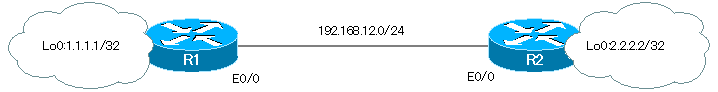
ネットワーク構成
設定条件
- R1/R2でOSPFv3によってIPv4のルーティングを行います。
- R1/R2のIPv6アドレスはリンクローカルアドレスFE80::X(X=ルータID)のみ設定します。
- 各ルータのルータIDはX.X.X.X(X=ルータ番号)とします。また、R1をDRとします。
- 高速なインタフェースに対応できるように適切な設定を行います。
初期設定
R1/R2には、それぞれホスト名とIPv4アドレスのみを設定しています。
R1 初期設定抜粋(Click)
hostname R1
!
interface Loopback0
 ip address 1.1.1.1 255.255.255.255
!
interface Ethernet0/0
 ip address 192.168.12.1 255.255.255.0
R2 初期設定抜粋(Click)
hostname R2
!
interface Loopback0
 ip address 2.2.2.2 255.255.255.255
!
interface Ethernet0/0
 ip address 192.168.12.2 255.255.255.0
設定と確認
Step1:IPv6ルーティングの有効化
OSPFv3パケットはIPv6で転送するため、IPv6ルーティングを有効にしてIPv6アドレスが必要です。IPv6ルーティングを有効にせずに、OSPFv3ルーティングプロセスを起動しようとするとできません。
R1 OSPFv3プロセスを有効化できない
R1(config)#router ospfv3 1
%OSPFv3: IPv6 routing not enabled
R1/R2でIPv6ルーティングを有効にして、インタフェースにリンクローカルアドレスを設定します。
R1 IPv6ルーティングの有効化
ipv6 unicast-routing
!
interface Loopback0
 ipv6 address FE80::1 link-local
!
interface Ethernet0/0
 ipv6 address FE80::1 link-local
R2 IPv6ルーティングの有効化
ipv6 unicast-routing
!
interface Loopback0
 ipv6 address FE80::2 link-local
!
interface Ethernet0/0
 ipv6 address FE80::2 link-local
関連記事
Step2:OSPFv3 for IPv4の設定
R1/R2でOSPFv3ルーティングプロセスを有効にします。IPv4のルーティングを行うため、IPv4のAddress-familyを有効化します。そして、インタフェースでOSPFv3 for IPv4を有効化します。
R1 OSPFv3 for IPv4
router ospfv3 1
 router-id 1.1.1.1
 address-family ipv4
!
interface Loopback0
 ospfv3 1 ipv4 area 0
!
interface Ethernet0/0
 ospfv3 1 ipv4 area 0
R2 OSPFv3 for IPv4
router ospfv3 1
 router-id 2.2.2.2
 address-family ipv4
!
interface Loopback0
 ospfv3 1 ipv4 area 0
!
interface Ethernet0/0
 ospfv3 1 ipv4 area 0
これで、R1/R2での基本的なOSPFv3 for IPv4の設定は完了です。IPv4の通信が可能です。
Step3:OSPFv3 for IPv4の確認
OSPFv3 for IPv4の動作を確認します。以下のshowコマンドを利用します。
- show ospfv3 interface brief
- show ospfv3 neighbor
- show ospfv3 database
- show ip route ospfv3
R1では、次のようなshowコマンドの結果です。
R1 OSPFv3 for IPv4の確認
R1#show ospfv3 interface brief
Interface    PID   Area            AF         Cost  State Nbrs F/C
Lo0          1     0               ipv4       1     LOOP  0/0
Et0/0        1     0               ipv4       10    BDR   1/1
R1#show ospfv3 neighbor

          OSPFv3 1 address-family ipv4 (router-id 1.1.1.1)

Neighbor ID     Pri   State           Dead Time   Interface ID    Interface
2.2.2.2           1   FULL/DR         00:00:32    3               Ethernet0/0
R1#show ospfv3 database

          OSPFv3 1 address-family ipv4 (router-id 1.1.1.1)

                Router Link States (Area 0)

ADV Router       Age         Seq#        Fragment ID  Link count  Bits
 1.1.1.1         207         0x80000002  0            1           None
 2.2.2.2         208         0x80000002  0            1           None

                Net Link States (Area 0)

ADV Router       Age         Seq#        Link ID    Rtr count
 2.2.2.2         208         0x80000001  3          2

                Link (Type-8) Link States (Area 0)

ADV Router       Age         Seq#        Link ID    Interface
 1.1.1.1         263         0x80000001  3          Et0/0
 2.2.2.2         249         0x80000001  3          Et0/0

                Intra Area Prefix Link States (Area 0)

ADV Router       Age         Seq#        Link ID    Ref-lstype  Ref-LSID
 1.1.1.1         207         0x80000002  0          0x2001      0
 2.2.2.2         208         0x80000002  0          0x2001      0
 2.2.2.2         208         0x80000001  3072       0x2002      3
R1#show ip route ospfv3
Codes: L - local, C - connected, S - static, R - RIP, M - mobile, B - BGP
       D - EIGRP, EX - EIGRP external, O - OSPF, IA - OSPF inter area
       N1 - OSPF NSSA external type 1, N2 - OSPF NSSA external type 2
       E1 - OSPF external type 1, E2 - OSPF external type 2
       i - IS-IS, su - IS-IS summary, L1 - IS-IS level-1, L2 - IS-IS level-2
       ia - IS-IS inter area, * - candidate default, U - per-user static route
       o - ODR, P - periodic downloaded static route, H - NHRP, l - LISP
       a - application route
       + - replicated route, % - next hop override

Gateway of last resort is not set

      2.0.0.0/32 is subnetted, 1 subnets
O        2.2.2.2 [110/10] via 192.168.12.2, 00:04:01, Ethernet0/0
ルーティングテーブルが完成しているので、R1-R2間のIPv4の通信ができます。R1 Lo0(1.1.1.1)からR2 Lo0(2.2.2.2)へPingすると、正常に応答が返ってきます。
R1からR2へPing
R1#ping 2.2.2.2 source 1.1.1.1
Type escape sequence to abort.
Sending 5, 100-byte ICMP Echos to 2.2.2.2, timeout is 2 seconds:
Packet sent with a source address of 1.1.1.1
!!!!!
Success rate is 100 percent (5/5), round-trip min/avg/max = 1/1/1 ms
Step4:DRの設定
R1-R2間のイーサネットリンクでは、現在、R2がDRです。R2のルータIDが大きいからです。R1がDRになるようにR1 E0/0 ルータプライオリティを大きくします。
R1 ルータプライオリティの設定
interface Ethernet0/0
 ospfv3 1 priority 255
ルータプライオリティを設定したあと、再度、DRの選出を行うようにOSPFv3プロセスをクリアします。現在のDRであるR2でクリアします。
R2 OSPFv3プロセスのクリア
R2#clear ospfv3 1 process
Reset selected OSPFv3 processes? [no]: yes
Step5:DRの確認
R1でshow ospfv3 interface E0/0コマンドを見ると、R1がDRになっていることがわかります。
R1 show ospfv3 interface
R1#show ospfv3 interface Ethernet 0/0
Ethernet0/0 is up, line protocol is up
  Link Local Address FE80::1, Interface ID 3
  Internet Address 192.168.12.1/24
  Area 0, Process ID 1, Instance ID 64, Router ID 1.1.1.1
  Network Type BROADCAST, Cost: 10
  Transmit Delay is 1 sec, State DR, Priority 255
  Designated Router (ID) 1.1.1.1, local address FE80::1
  Backup Designated router (ID) 2.2.2.2, local address FE80::2
  Timer intervals configured, Hello 10, Dead 40, Wait 40, Retransmit 5
    Hello due in 00:00:02
  Graceful restart helper support enabled
  Index 1/2/2, flood queue length 0
  Next 0x0(0)/0x0(0)/0x0(0)
  Last flood scan length is 0, maximum is 3
  Last flood scan time is 0 msec, maximum is 0 msec
  Neighbor Count is 1, Adjacent neighbor count is 1
    Adjacent with neighbor 2.2.2.2  (Backup Designated Router)
  Suppress hello for 0 neighbor(s)
Step6:auto-cost reference-bandwidthの設定
この設定例のネットワーク構成は、10Mbpsのイーサネットインタフェースを利用しています。しかし、ギガビットイーサネットなどのより高速なインタフェースを利用する場合に備えて、きちんとコスト計算に反映させるべきです。コスト計算式の分子の値を変更します。
R1/R2 auto-cost reference-bandwidthの設定
router ospfv3 1
 address-family ipv4 unicast
  auto-cost reference-bandwidth 5000
Step7:コストの確認
コスト計算式の分子が変更されて、各インタフェースのコストの値が変わっていることを確認します。次のコマンドを利用します。
- show ospfv3 | include Reference bandwidth
- show ospfv3 interface brief
R1でのshowコマンドの結果は以下のようになります。
R1 コストの確認
R1#show ospfv3 | include Reference bandwidth
 Reference bandwidth unit is 5000 mbps
R1#show ospfv3 interface brief
Interface    PID   Area            AF         Cost  State Nbrs F/C
Lo0          1     0               ipv4       1     LOOP  0/0
Et0/0        1     0               ipv4       500   DR    1/1
設定コマンドのまとめ
初期設定の状態から、ここまでのStepでR1/R2に設定したコマンドをまとめます。
R1 OSPFv3 for IPv4 設定コマンドのまとめ
ipv6 unicast-routing
!
interface Loopback0
 ipv6 address FE80::1 link-local
 ospfv3 1 ipv4 area 0
!
interface Ethernet0/0
 ipv6 address FE80::1 link-local
 ospfv3 1 priority 255
 ospfv3 1 ipv4 area 0
!
router ospfv3 1
 router-id 1.1.1.1
 !
 address-family ipv4 unicast
  auto-cost reference-bandwidth 5000
 exit-address-family
!
R2 OSPFv3 for IPv4 設定コマンドのまとめ
ipv6 unicast-routing
!
interface Loopback0
 ipv6 address FE80::2 link-local
 ospfv3 1 ipv4 area 0
!
interface Ethernet0/0
 ipv6 address FE80::2 link-local
 ospfv3 1 ipv4 area 0
!
router ospfv3 1
 router-id 2.2.2.2
 !
 address-family ipv4 unicast
  auto-cost reference-bandwidth 5000
 exit-address-family
!

OSPFの仕組み
- OSPFとは? 初心者にもわかりやすくOSPFの特徴を解説
- OSPFの処理の流れ
- OSPFルータID ~OSPFルータを識別~
- OSPFルータのルータIDが重複してしまったら?
- OSPF ネイバーとアジャセンシー
- OSPF DR/BDR
- イーサネット上のshow ip ospf neighborの見え方
- OSPFネットワークタイプ ~OSPFが有効なインタフェースの分類~
- OSPF LSDBの同期処理
- 大規模なOSPFネットワークの問題点
- OSPFエリア ~エリア内は詳しく、エリア外は概要だけ~
- OSPFルータの種類
- OSPF LSAの種類
- OSPF エリアの種類
- OSPFの基本的な設定と確認コマンド [Cisco]
- インタフェースでOSPFを有効化することの詳細
- OSPF ループバックインタフェースのアドバタイズ
- OSPF Hello/Deadインターバルの設定と確認コマンド
- OSPFコストの設定と確認
- OSPFルータプライオリティの設定と確認コマンド
- OSPFネイバー認証の設定 ~正規のルータとのみネイバーになる~
- バーチャルリンク上のネイバー認証
- OSPF スタブエリアの設定と確認[Cisco]
- OSPF スタブエリアの設定例 [Cisco]
- OSPFデフォルトルートの生成 ~default-information originateコマンド~
- OSPFデフォルトルートの生成 ~スタブエリア~
- OSPF バーチャルリンク ~仮想的なエリア0のポイントツーポイントリンク~
- OSPF バーチャルリンクの設定と確認 [Cisco]
- OSPF バーチャルリンクの設定例 [Cisco]
- OSPF 不連続バックボーンのVirtual-link設定例
- OSPFのルート集約と設定
- OSPFルート集約の設定例(Cisco)
- OSPF ルート種類による優先順位
- OSPFネイバーの状態がExstartでスタックする原因
- OSPFパケットの種類とOSPFヘッダフォーマット
- OSPF Helloパケット
- OSPF DD(Database Description)パケット
- OSPF LSR(Link State Request)パケット
- OSPF LSU(Link State Update)パケット
- OSPF LSAck(Link State Acknowledgement)パケット
- OSPF 再配送ルートの制限 ~redistribute maximum-prefixコマンド~
- OSPFでのディストリビュートリスト/プレフィクスリストの動作
- OSPFでのディストリビュートリストの設定例 Part1
- OSPFでのディストリビュートリストの設定例 Part2
- OSPFのLSAフィルタの概要 ~LSAタイプ3/タイプ5をフィルタ~
- LSAタイプ3のフィルタ設定例
- LSAタイプ5のフィルタ設定例
- 3階層モデルLANのOSPFルーティング
- 演習:実践的なOSPFルーティング Part1:OSPFの基本設定
- 演習:実践的なOSPFルーティング Part2:デフォルトルートの生成
- 演習:実践的なOSPFルーティング Part3:スタブエリア
- 演習:実践的なOSPFルーティング Part4:ルート集約
- 演習:実践的なOSPFルーティング Part5:トラブルシューティング
- OSPF 設定ミスの切り分けと修正 Part1
- OSPF 設定ミスの切り分けと修正 Part2
- OSPF 設定ミスの切り分けと修正 Part3
- OSPF 設定ミスの切り分けと修正 Part4
- OSPF 設定ミスの切り分けと修正 Part5
- OSPF 設定ミスの切り分けと修正 Part6
- Cisco OSPFv3 for IPv4の設定と確認コマンド
- Cisco OSPFv3 for IPv4の設定例
- OSPFv3の設定例 [Cisco]
- OSPFv3 ルート集約の設定例 [Cisco]